![]()
To install globally as a uv tool,
uv tool install git+https://github.com/henrynoyes/robot-diff.gitFor development, clone and run,
uv sync --dev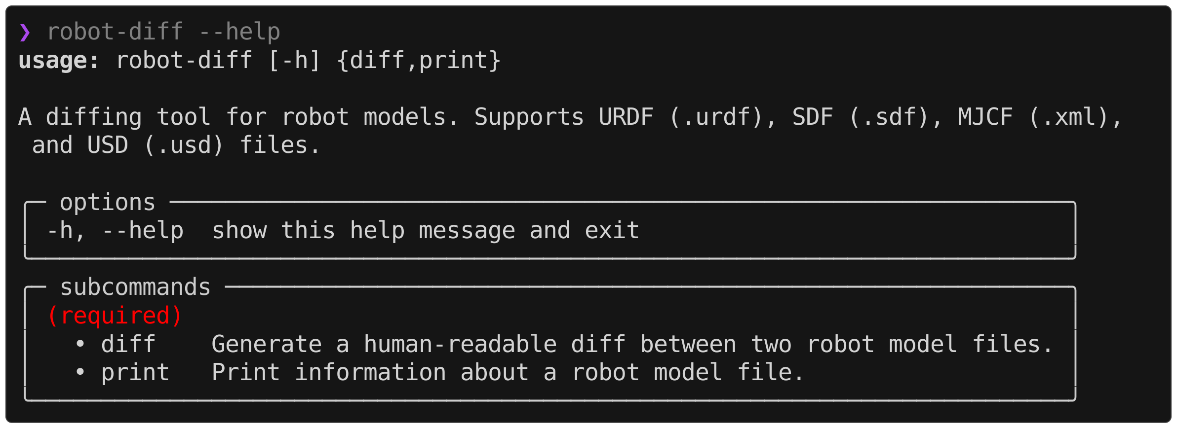
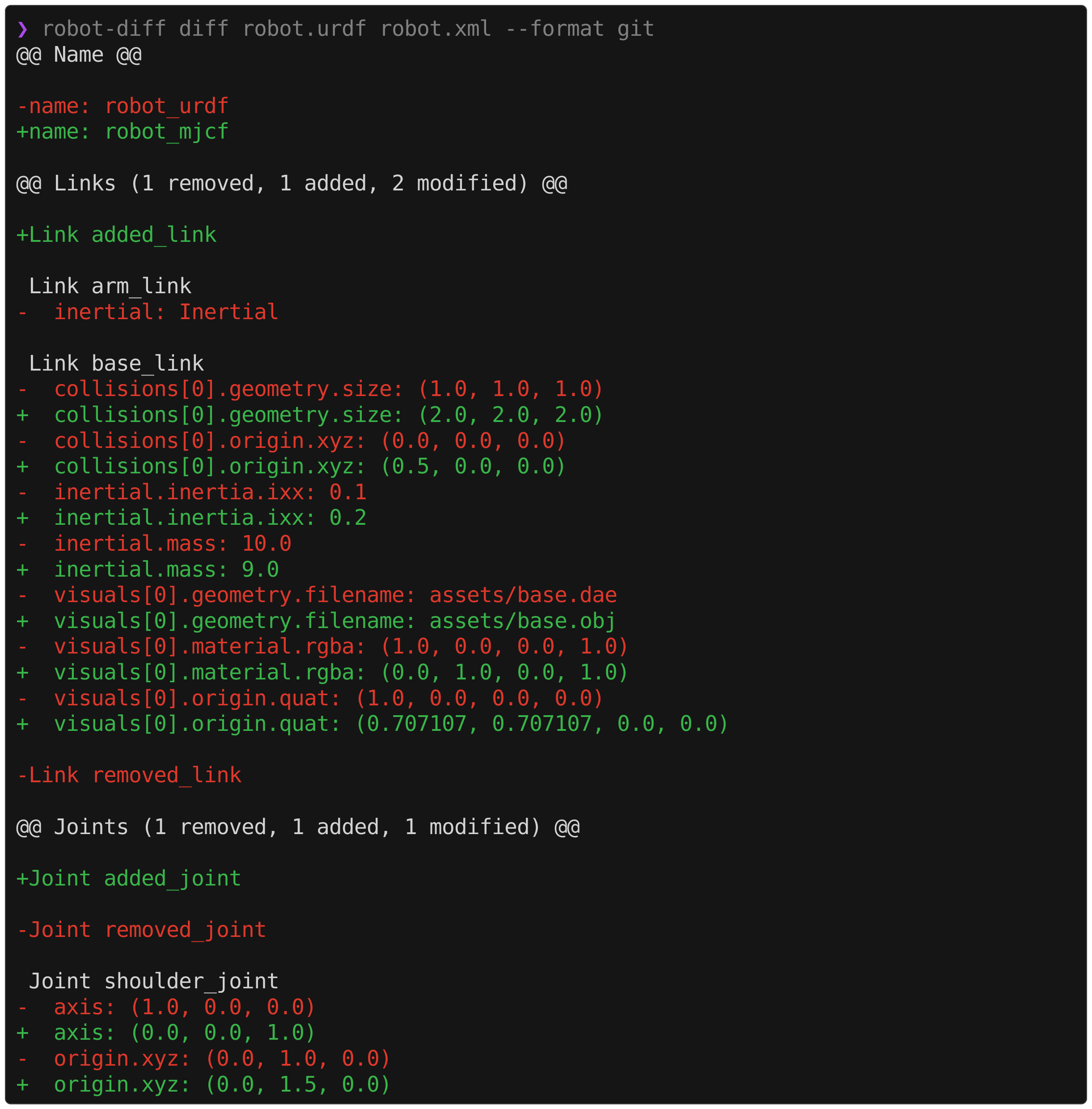
robot-diff diff robot.urdf robot.xml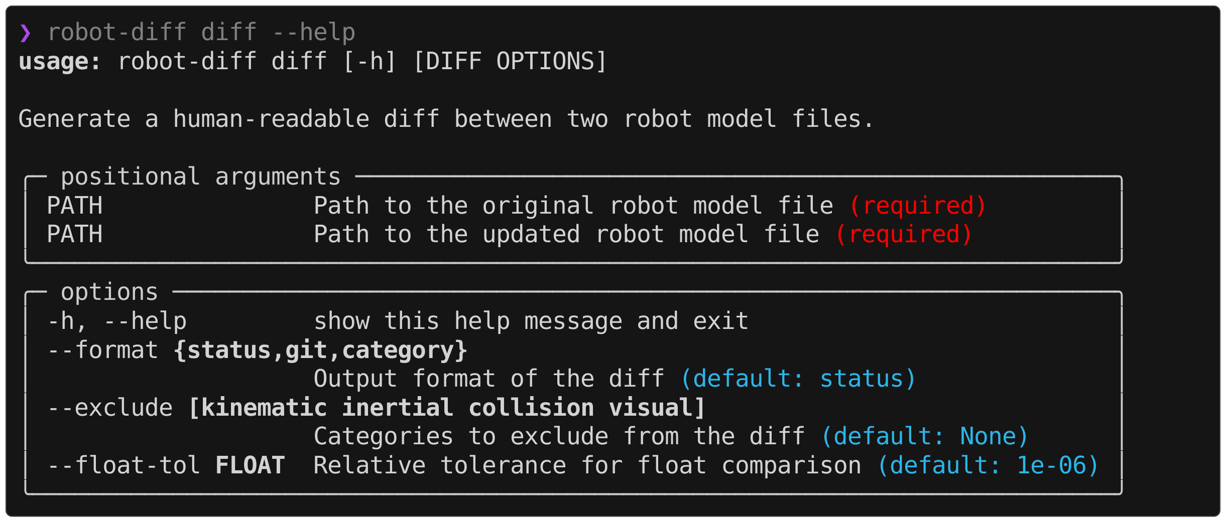
The diff information is divided into four categories: kinematic, inertial, collision, and visual. The CLI supports adjusting the displayed categories on an exclusion-first basis, e.g.,
robot-diff diff robot.urdf robot.xml --exclude visual collisionIn the case where two robot models intentionally reference different visual meshes (e.g., .dae in URDF and .obj in MJCF), suppressing the visual diffs can help isolate the relevant information in the output.
robot-diff supports three different formats out of the box and contains an extensible interface to define custom formatters. At runtime, the information about the diff between two robot models is parsed into a RobotDiff object, which can then be digested and printed by various formatters. The desired format can be specified in the CLI by,
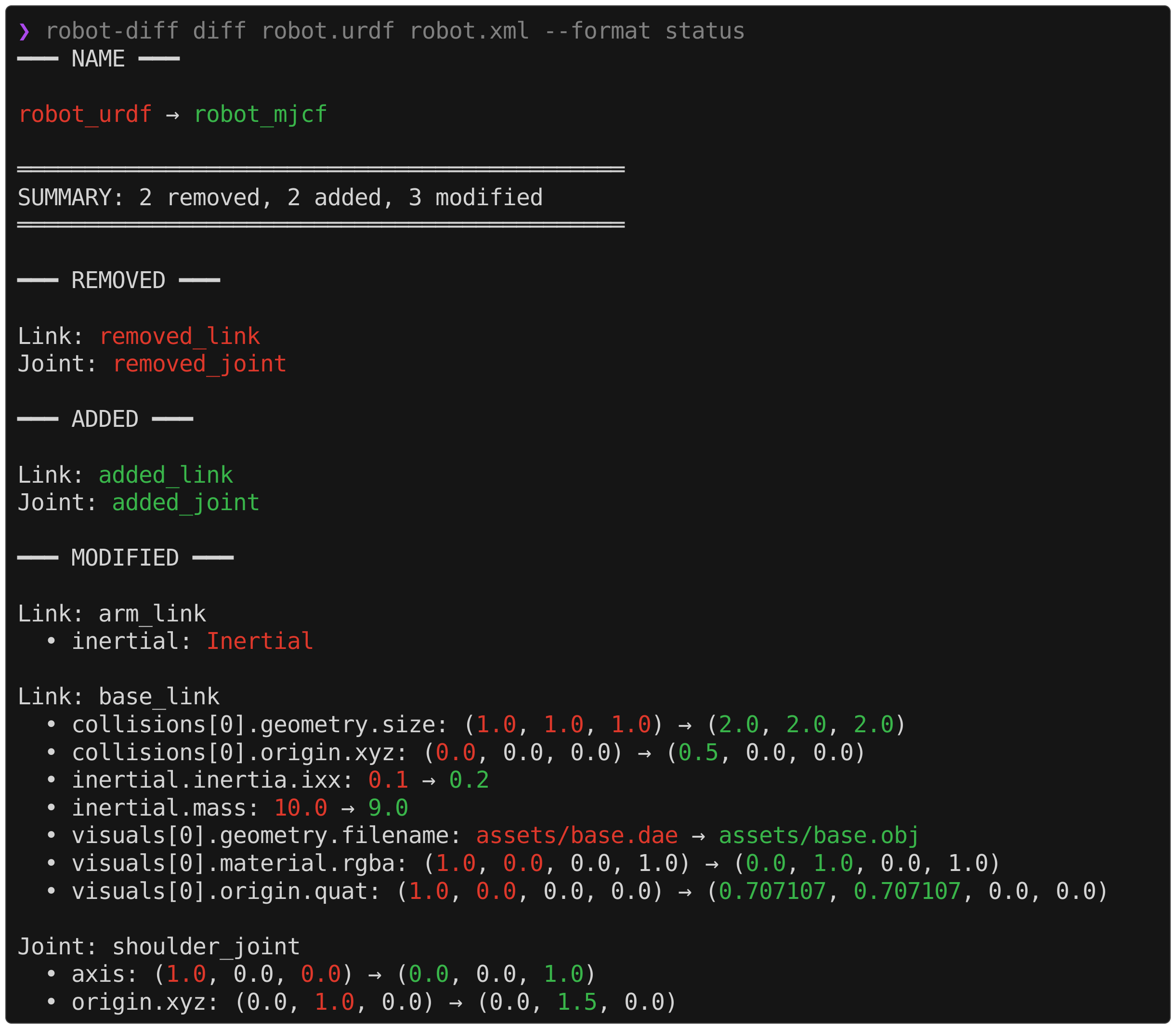
robot-diff diff robot.urdf robot.xml --format {format}The default formats are shown below,
status
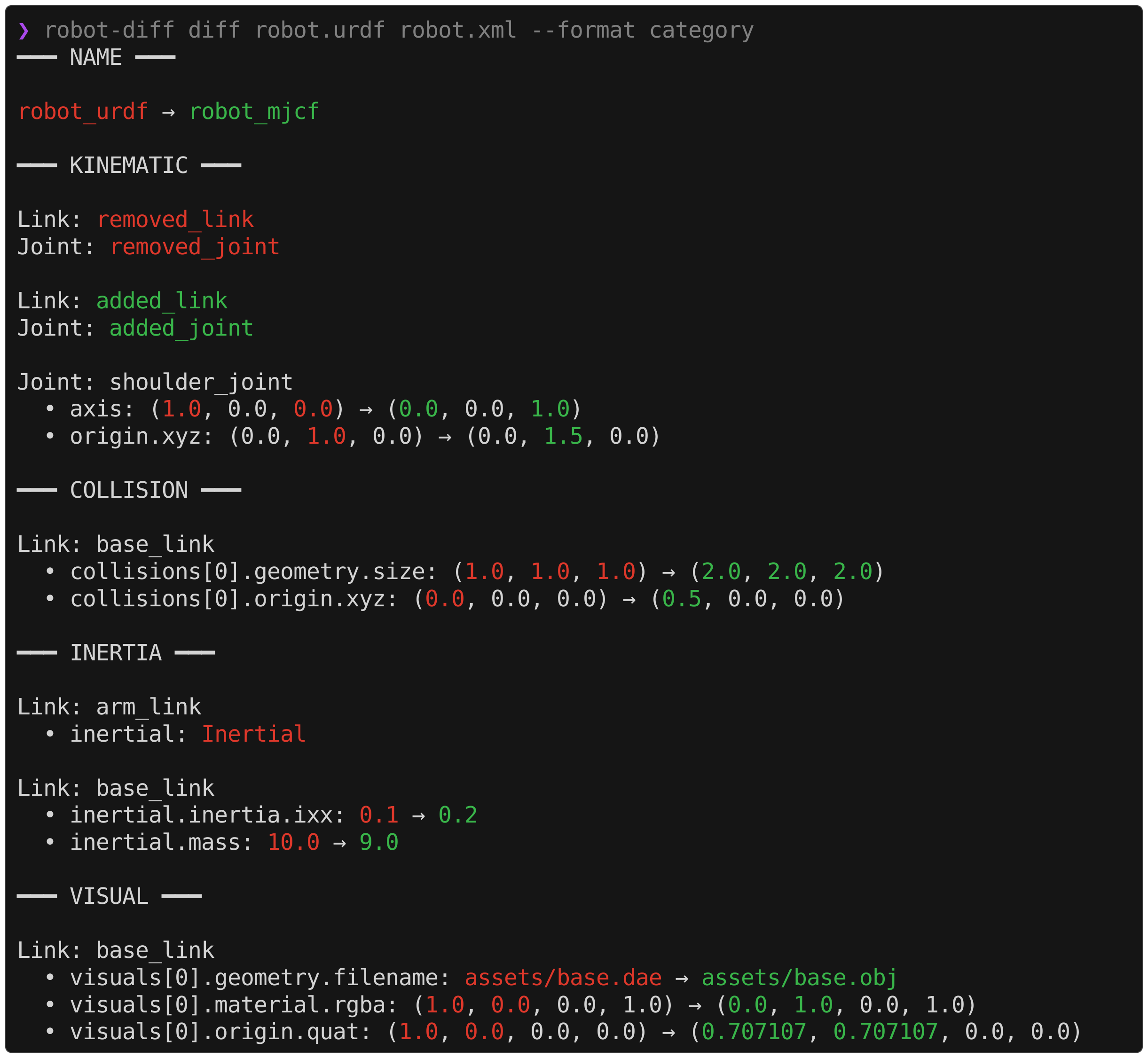
category
git
A custom formatter can be constructed by defining a class that takes in a RobotDiff object and implements a format() method. Optionally, this can inherit from the base StringFormatter class which contains helpers for parsing values and formatting strings.
robot-diff print robot.urdf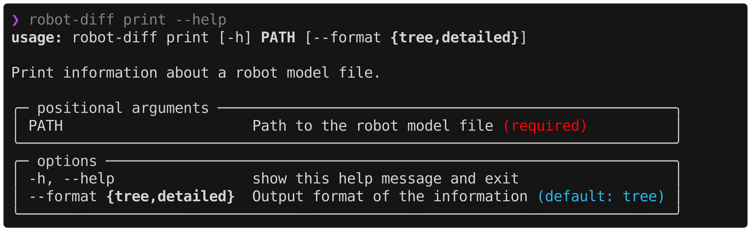
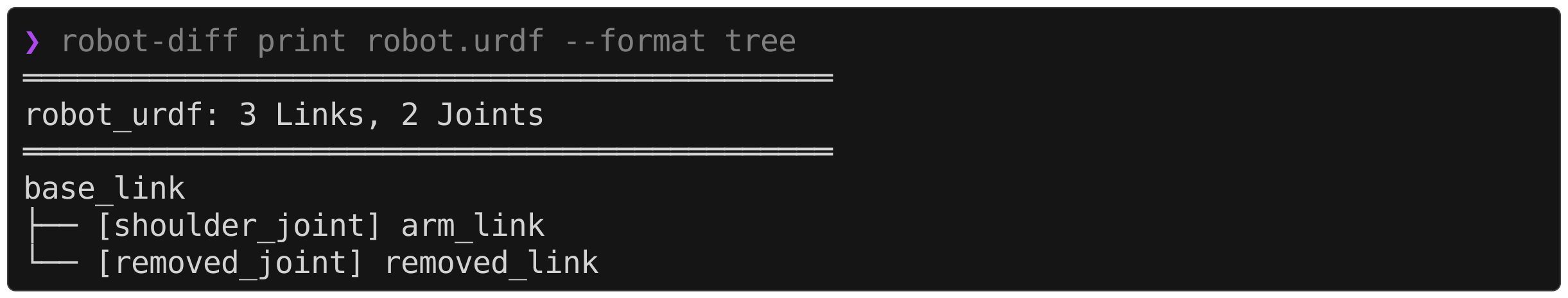
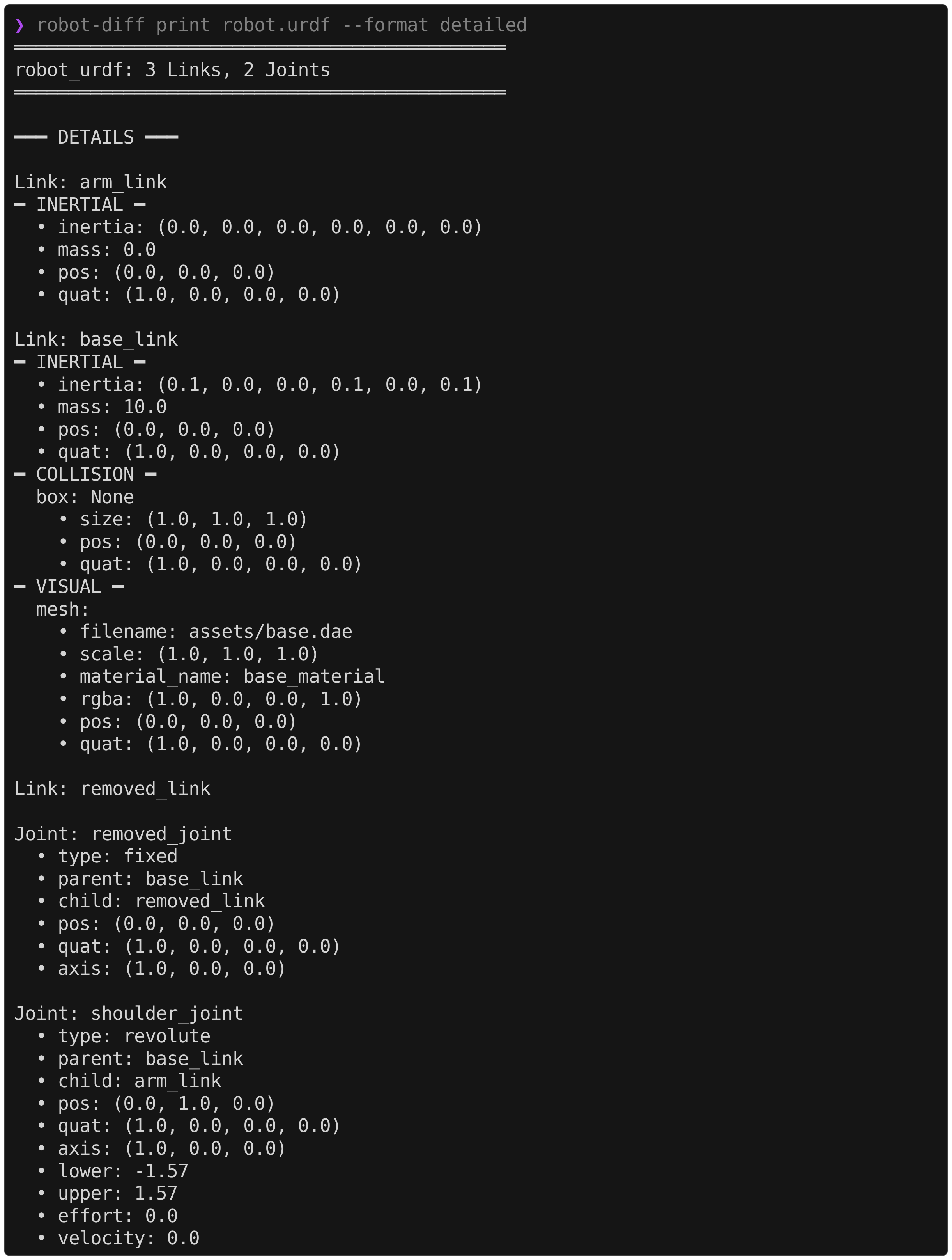
A single robot model file can be printed in two different formats. This can be useful for debugging which information was parsed into the internal Robot representation.
tree
detailed
The URDF parser does not assume any special conventions for input files.
The SDF parser assumes a URDF-style construction for the link and joint poses. I.e., link poses are always defined as the identity relative to the parent joint, and joint poses are always defined relative to the parent link.
<sdf version="1.12">
  <model name="robot">
    <link name="base_link"/> <!-- base link has no parent joint -->
    <link name="link_1">
      <pose relative_to="joint_1"/>
    </link>

    <joint name="joint_1" type="revolute">
      <pose relative_to="base_link">1 2 3 0 0 0</pose>
      <parent>base_link</parent>
      <child>link_1</child>
    </joint>
  </model>
</sdf>
Notably, this is the style generated by gz sdf robot.urdf > robot.sdf from the SDFormat library. These conditions are validated by checks in the parser.
if pose_elem is None or pose_elem.get("relative_to") != parent:
    raise ValueError(f"Joint '{name}' pose must have relative_to='{parent}'")
if pose_elem is None or pose_elem.get("relative_to") != parent_joint:
raise ValueError(f"Link '{name}' pose must have relative_to='{parent_joint}'")
...
if pose.xyz != (0.0, 0.0, 0.0) or pose.quat != (1.0, 0.0, 0.0, 0.0):
raise ValueError(f"Link '{name}' pose must be the identity")Admittedly, the SDF parser is likely the weakest of the four, as it is the format I have the least experience using. It could certainly be made stronger by handling arbitrary pose constructions (see future features). That being said, I see little reason why most newly generated models could not follow the URDF-style convention.
The MJCF parser makes a few assumptions about the input model. First, it assumes that the collision and visual geometries are denoted with classes named "collision" and "visual". A common approach is to set separate geom groups for each and disable collisions for the visual class as shown below,
<mujoco model="robot">
  <default>
    <default class="collision">
      <geom group="0"/>
    </default>
    <default class="visual">
      <geom type="mesh" contype="0" conaffinity="0" group="1"/>
    </default>
  </default>
</mujoco>
The parser also respects class inheritance, for example,
<mujoco model="robot">
  <default>
    <default class="collision">
      <geom group="0"/>
      <default class="foot">
        <geom type="sphere" priority="1" condim="6"/>
      </default>
    </default>
    <default class="visual">
      <geom type="mesh" contype="0" conaffinity="0" group="1"/>
    </default>
  </default>
</mujoco>
Any <geom> that is not denoted as a visual or collision geometry is ignored by the parser.
The other small assumption concerns the declaration of materials for meshes. Though it is possible to define a material as a material attribute in a <mesh> element, this information is not parsed.
<asset>
  <material name="red" rgba="1.0 0.0 0.0 1"/>
  <mesh file="body.obj" material="red"/> <!-- not supported -->
</asset>
Instead, the material attribute of the associated <geom> element is parsed. This convention is much more readable and is standard practice.
<asset>
  <material name="red" rgba="1.0 0.0 0.0 1"/>
  <mesh file="body.obj"/>
</asset>
...
<geom mesh="body" material="red" class="visual"/> <!-- supported -->Since USD is a significantly capable ecosystem that has applications far beyond robot modeling, strong assumptions are made about the input asset format. The implemented USD parser is configured to ingest assets in the format adopted by Isaac Sim 5.1+. Specifically, this format defines a flattened scene graph with the file structure,
<name>.usda
configuration/
├── <name>_base.usdc
├── <name>_physics.usda
├── <name>_robot.usda
└── <name>_sensor.usda
where the Physics, Robot, and Sensor Variant Sets encode the relevant information using the Isaac Robot Schema. The .usda/.usdc file extensions[1] are adopted to follow the OpenUSD best practices. In the future, this implementation could be expanded to other USD structures such as the hierarchical style produced by the mujoco-usd-converter. Due to the immaturity of such alternative formats, this was not included in the initial release.
[1] They can be automatically generated using this codify-usd.sh script, though this is not necessary as the file extensions do not influence parsing.
In the XML formats, meshes are included by referencing an external file such as base.stl. For geometric formats like .obj or .stl, only vertex information is stored, meaning material information must be specified in the robot model. However, there are other 3D asset formats that do store material information inside the mesh file, e.g., .dae and .gltf. When these types of meshes are implemented in a robot description, the associated parsers are unable to extract the material information and thus do not detect asset-level diffs[2]. This is by design, as robot-diff is built to detect diffs in the robot model, not in the referenced assets.
In a USD asset, the meshes are typically encoded as instanceable in a binary stage file like <name>_base.usdc. Similar to the advanced formats mentioned earlier, the material information can be encoded in the Mesh prim as GeomSubsets, meaning they do not conform to the structure defined by a Visual object. Therefore, the behavior here is analogous, and asset-level changes in the meshes of a USD are not detected by the parser[2].
[2] The one "asset-level" exception being a filename change.
Visit the appendix for a more verbose discussion on the justification for robot-diff.
-
Support arbitrary pose declaration in
SDFParser -
Add conversion between XML formats with
robot-diff convert(leave USD creation to Isaac and Newton for now)
To manually lint/format,
uv run ruff check --fix .
uv run ruff format .
Ruff is also configured as a pre-commit
To run tests,
uv run pytest
To type check,
uv run ty checkTo build a release,
uv build # generates wheel and source in dist/