Copyright (c) 2016, Michael Ogg
DoorOpener was designed by Dr. Michael Ogg with the intention of creating a hands-free method of entering or exiting one’s house. It was documented by the Ryerson Chapter of Tetra. DoorOpener is built for a user with limited or no limb mobility but has wheelchair access. It is based around the use of a Raspberry Pi, a Z-wave Home Automation Controller, RFID tags and pressure plates. The objective of having the code, as well as additional information, on Github is to allow users to copy and modify Dr. Ogg’s solution for their own purposes.
This project assumes you have a basic understanding of the following concepts: electrical work, Raspberry Pi, Z-wave controllers, and Python. The files are designed so that you can copy and paste this solution almost directly with only minor changes to the config file, given that the hardware is laid out in the same manner.
We hope that for whatever reason, whether it be as an electronic hobbyist or as someone working in accessibility services, you can make use of Dr. Ogg’s solution. If you’d like to see a video of the DoorOpener, please click here: https://www.youtube.com/watch?v=-B-Js19Npv0
DoorOpener relies on two main controllers: the Raspberry Pi, which controls the majority of the project, and the Vera MiCasaVerde Z-wave controller, which controls the door lock.
The RFID tag readers control if the door is locked or unlocked (based on commands sent from the Pi to the Vera to the Z-wave door lock). Since there is a reader on both the inside and outside of the house, it is possible to change the state of the lock from either side of the door.
The pushplates activate the door opening by activating the latch strike relay and then door operator relay through the Pi. The door closes automatically after a set period of time (declared in the CONFIG file). In addition to the pushplates, there is a Z-wave relay (commonly referred to as a "Compatabile Contact Closure") which can open the door through a Z-wave app (controlled by a device such as an iPhone or Android). The pushplates and the Z-wave relay are all wired in parallel to the Pi via a 3.5 mono jack and a Swifty USB.
The Pi communicates with the Vera via URL commands (based on API given from Vera) sent via WiFi. This allows the Pi to control the door locker and is the middleman between the Z-wave relay and the Vera itself.
The Pi itself is controlled through threaded Python files, which means all the components are running simultaneously.
Raspberry Pi: Main controller that connects to the Vera MiCasaVerde and all other components.RFID Readerx2 : Device used to read RFID tags.Latch Strike Relay: Relay used to open the door latch. (Contained in relay box).Door Operator Relay: Similar to the strike relay. Used to signal the door operator to begin opening. (Contained in relay box).Z-wave Door Lock: A Z-wave controlled lock which locks/unlocks based on the RFID readers.Vera MiCasaVerde: Z-Wave hub that controls the door lock.Z-Wave Compatible Contact Closure (Z-wave Relay): a relay that allows the door to be opened and close via Z-wave.Pushplatesx4 : In this project, four pushplates are used as switches to actuate the door open relay. One is installed at an average height and the other is installed at foot level height both inside and outside the house.Swifty USB Contact Sensor: a USB switch interface which detects contact closure. Takes a 3.5 mono jack input.
More information on the components can be found under the Hardware Choices section. Pictures of this set up have been included under Images.
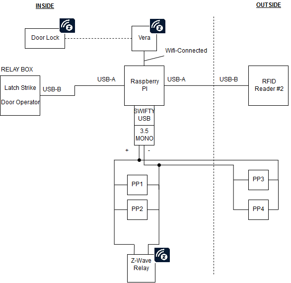
- 'PP' refers to pushplate.
- The black icon Z icon implies the devices using Z-wave.
This assumes that the hardware has been installed and all of the electrical connections have been made. There are three logical components of the door opener. These are:
- The door opening mechanism and push plates including electric strike.
- The RFID tag reader, Z-wave door locks and Z-wave hub.
- The Z-wave relay for opening the door with a Z-wave app or an Amazon Echo device.
Depending on needs the only component that is strictly essential is (1). If this is the case, depending on the door opener hardware and the electric strike used, it may be possible to do it just by programming the door opener itself. However, computer control is much more flexible and much easier to adjust parameters such as delays for door opening and closing.
Presumably most people will want to incorporate item (2) as well. This item could be used just as a method of access control although of course I designed the system to open my house door. This system uses the Vera Z-wave hub, https://getvera.com. There are several other Z-wave hubs on the market and in principle this can be used with any of them as long as there is a public HTTP interface.
With items (1) and (2) in place, item (3) required no extra work and was just icing. It’s a good idea to have multiple redundancy anyway so it just adds to the system. Item (3) assumes that home automation using an Amazon Echo device is already in place. Details of integrating that with the Vera Z-wave hub are described in another GitHub project, https://github.com/bwssytems/ha-bridge
- Download and install the zip file in /home/pi on the Raspberry pi. If a different directory/username is used, the initialization shell script door.sh will need to be changed appropriately. This will create the directory DoorOpener containing all the necessary files. (Any other computer can be used, but YMMV.) Python is usually included with the default installation on the raspberry pi.
1a. [as soon as I switch over from using package wget to package requests, this step will no longer be necessary but for now… ]
$ sudo pip install wget
- Change directory to DoorOpener and look at the file CONFIG. It is likely that some of the parameters will need changing. Each line represents one parameter and the syntax of the line is: parameter name followed by parameter values specific to that parameter separated by whitespace. Everything after a # is treated as a comment and the rest of the line is ignored. The file included in the distribution looks like:
DEBUG		True			# debug flag, True/False

rfidReader	/dev/ttyUSB0 /dev/ttyUSB1	# list of rfidReader devices
strikeRelay	/dev/ttyUSB2 1 4	# relay 1, hold 4 sec
doorRelay	/dev/ttyUSB2 2 1	# relay 2, hold 1 sec
contactSensor	/dev/input/mouse0 9 0 0	# close [9,0,0], open [8,0,0]
# contactSensor	/dev/hidraw0 1 0 0	# close [1,0,0], open [0,0,0]
openDelay	1.5			# time delay for door to open
rfidDB		rfid.db			# file of allowed RFID tags

vera		http://192.168.1.13:3480	# IP:port of Vera hub
doorId		16				# zwave ID of door lock
The parameters that will almost certainly need changing are: rfidReader, strikeRelay, doorRelay, contactSensor, vera and doorId.
All of the USB devices will have a corresponding /dev entry. The easiest way to find them is to unplug all of the USB devices, and give the command:
$ lsusb
Then plug them back in one at a time, each time giving the same command to establish that the device was correctly recognized. When they are all plugged in, the output should look something like:
Bus 001 Device 009: ID 0403:6001 Future Technology Devices International, Ltd FT232 USB-Serial (UART) IC
Bus 001 Device 008: ID 0403:6001 Future Technology Devices International, Ltd FT232 USB-Serial (UART) IC
Bus 001 Device 007: ID 0403:6001 Future Technology Devices International, Ltd FT232 USB-Serial (UART) IC
Bus 001 Device 006: ID 0a95:0010
Bus 001 Device 005: ID 058f:6254 Alcor Micro Corp. USB Hub
Bus 001 Device 004: ID 0bda:8176 Realtek Semiconductor Corp. RTL8188CUS 802.11n WLAN Adapter
Bus 001 Device 003: ID 0424:ec00 Standard Microsystems Corp. SMSC9512/9514 Fast Ethernet Adapter
Bus 001 Device 002: ID 0424:9514 Standard Microsystems Corp.
Bus 001 Device 001: ID 1d6b:0002 Linux Foundation 2.0 root hub
Conveniently, both the RFID readers and the relays use the FTDI USB chip which makes the device appear as a TTY device. This is not only much easier to use than other USB devices but also makes it easy to identify. The following command will discover them:
$ ls /dev/ttyUSB*
/dev/ttyUSB0
/dev/ttyUSB1
/dev/ttyUSB2
In this example, USB0 and USB1 are the two RFID readers and USB2 is the dual relay. Note that the dual relay used here has one USB connection and therefore one FTDI chip. Each of the two relays is identified by the second value of the relay parameter line in the CONFIG file. The USB device for the contact sensor from Origin Instruments is slightly more difficult to detect because the chip does not have any manufacturer identification when it identifies itself to the raspberry pi. Here it appears as device 006 on bus 001. The DIP switches on the device allow it to be configured as a mouse or keyboard and the documentation says that it is a standard HID device. Therefore we can look in /dev for these types of device.
$ ls /dev/input/mouse*
/dev/input/mouse0
And for the HID,
$ ls /dev/hidraw*
/dev/hidraw0
Plugging and unplugging the device will confirm that we have the right one. The open and close codes are specified in the CONFIG file. For a different device, they should be able to be found from the test program provided.
The openDelay parameter is the time delay between the strike relay closing and the open door relay closing since the door strike does not operate instantly. The value in the CONFIG file may be sufficient but depending on the hardware, it might need adjusting.
The rfidDB parameter is the name of the file containing the authorized tags. If you wanted, you could make a log file of the door entries to keep track of everyone who entered. You could even make a log entry for all entry attempts to see who had tried to enter and was perhaps no longer authorized to do so.
The vera parameter is the IP address and port number of the vera hub. The vera hub should be assigned a static IP address. A future release might obtain these values by discovery which the protocol allows.
The doorId parameter is the Z-wave ID of the door lock assigned by the vera hub during the Z-wave pairing. It can be found by entering the URL http://hub_IP_address:port/data_request?id=sdata&output_format=json into a web browser. If the port is not known it is most likely 3480 which is the default port of the vera hub. This gives a dump of all the devices in the vera hub but the door lock should be readily identifiable by its name or type.
- There are some test programs to test basic operation and configuration.
testoggle.py: Test the configuration and the Z-wave operation of lock by toggling the lock state. Operation:
$ ./testoggle.py
This test will change the state of the lock each time it is run. It only needs the Z-wave installation but not the door opener installation.
testrelay.py: Test the configuration and operation of the relays. Operation:
$ ./testrelay.py
This test will work even if none of the installation is done but just with the raspberry pi and the USB relays. It can be used for incremental testing during installation, e.g. just with the door strike alone, the door operator alone and finally both together.
testcontact.py: Test the configuration and operation of the contact sensor. Operation:
$ ./testcontact.py
This test will work even if none of the installation is done but just with the raspberry pi, the USB relays and the contact sensor connected. It can be used for incremental testing during installation, e.g. just with the door strike alone, the door operator alone and finally both together. If the Z-wave relay is used, now would be a good time to test it. Use an appropriate Z-wave app, e.g. HomeWave, http://homewave.intvelt.com/ and write a “momentary on“ macro for the relay with a one second pause between closing and opening. At this point, the rest of the installation can be completed including all the push plates connected in parallel with the Z-wave relay. The system can again be tested.
doormain.py: System testing and operation of the RFID readers as well as adding new tags to the RFID file. Operation:
$ ./python doormain.py
Set the DEBUG parameter to True in the CONFIG file, and hold an RFID tag 3” or less in front of a reader. The reader will beep if the tag was read successfully and the tag’s code will print out on the console. Add this code to the file specified by rfidDB then run the program again. This time the lock state should toggle and the door will open if any of the push plates is pressed or the Z-wave relay is closed using the Z-wave app.
- Installation can be finished so that the program is started and runs continuously after a reboot.
Copy door.sh to /etc/init.d/
$ sudo cp door.sh /etc/init.d/
Ensure that it has the right permissions:
$ cd /etc/init.d/
$ sudo chmod +x door.sh
Then create links in all the /etc/rc* directories:
$ sudo update-rc.d door.sh defaults
Reboot the raspberry pi and the door opener software should be running and ready to go.
- Using an Amazon Echo to open the door Having got this far, it’s easy to use the Amazon Echo to open the door. First, install the Vera-Phillips Hue bridge from GitHub project https://github.com/bwssytems/ha-bridge. The momentary on macro (or “scene”) should appear with the name “Open Sesame“ or whatever you called it. If not, open the GUI and manually add it as documented. Then say to your Amazon Echo: “Alexa discover devices“ and voilà, it’s all there! The only catch is that with this bridge, everything appears as a switch so you have to say something like: “Alexa Open Sesame on“ or perhaps “Alexa turn Open Sesame on.“
The DoorOpener software is self contained and complete, thus it doesn't require additional scripts or libraries to function. Depending on your hardware configuration, you may need to adjust several parts of the CONFIG file. As well, you must include your own RFID tag keys in the rfid.db. The following subsections explain the individual parts of the CONFIG file.
Please consult Pi documentation online for specific port names. Change the section of code after /dev/ (e.g. /dev/ttyUSB0) as required.
In the case where the timing of relay triggers and open delays are not optimal or do not function as desired, the following lines of the CONFIG file can be edited:
strikeRelay /dev/ttyUSB2 1 4    # relay 1, hold 4 sec
doorRelay   /dev/ttyUSB2 2 4    # relay 2, hold 1 sec
openDelay   1.5         # time delay for door to open
The strike relay holds the latch strike for 4 seconds which gives the door relay plenty of time to initiate the door operator sequence.
The contactSensor refers to the Z-wave Contact Closure (Relay).
contactSensor	/dev/input/mouse0 9 0 0	# close [9,0,0], open [8,0,0]
# contactSensor	/dev/hidraw0 1 0 0	# close [1,0,0], open [0,0,0]
You'll notice the contact closure is listed as a mouse, despite not being such a device. It so happens that the Pi can easily read the output of the contact closure easily (the 3 number sequences) as such when it is listed as a mouse, keyboard, or HIDRAW (as seen in the commented out line).
HIDRAW refers to human interface device (raw), which could also be used instead of 'mouse'. However, if listing the contact closure as a hidraw, the other two 3-number sequences must be used.
vera http://192.168.1.13:3480
Please consult your Vera documentation for obtaining the URL of your device.
doorID refers to the device number given to the door lock.
doorId 16
You'll have to access the Vera homepage via a browser to find out your door lock ID. Consult your Vera documentation to find the appropriate address / URL, and there will be a list of devices that can be connected or are already connected. The door lock ID will be listed there with a number.
All valid RFID key tags are stored in the rfid.db file and it can be opened in any plain text editor to add or remove key tags.
The intention of this section is to explain why the specific pieces of hardware were used, as well as to explain in further depth the particular components. Please note that although some decisions would not make sense from the perspective of a pure electronic hobbyist, the intention of the project was to make it as easy as possible to set up. This resulted in the purchase of a few extra components (such as the relay box) to minimize soldering / wiring and maximize the amount of 'plug-and-play'. This also resulted in increase portability across platforms.
Raspberry Pi 2
A Pi 2 was used with a Wi-Fi dongle, although a Pi 3 was used with built in wi-fi compatibility later by Dr. Ogg. Any Pi would do long as it has Wi-Fi or ethernet capabilities. It was used because of it's low-cost and minimal power usage, although in theory, any microprocessor / small computer could be used.
RFID Reader
A 125 kHz RFID reader was used. It had a solid range of 3 inches and a USB interface (via its FTDI connection) which was easily read out into a Linux TTY device. The specific RFID reader was used because it appears as a virtual COM (making it easy to interface with the Pi) and no driver installation was needed.
The following RFID system is composed of the following components: Reader: https://www.sparkfun.com/products/9963 Chip: https://www.sparkfun.com/products/11828 (this plugs into the above reader). Tags: https://www.sparkfun.com/products/retired/8310 The specific Sparkfun tags are retired, but any 125 kHz tag will do. Ensure that the tags you purchase are of the correct frequency.
USB Relay Box
Although the Pi has GPIO pins that the Latch Strike and Door Operator relays could connect directly, as mentioned previously, the priority was ease of set-up and use. This Relay box which connects via USB to the Pi allows the user to control two devices from the Pi directly. Please note that you still need to wire the Latch Strike and Door Operator into the relay correctly.
https://www.kmtronic.com/usb-relays.html?product_id=55
For information about wiring a device to the relay, we recommend reading the following article: https://electronics.stackexchange.com/questions/30952/can-you-clarify-what-an-1no1nc-switch-is
Latch Strike Relay
An electric latch strike was required to strike the latch of the door before the door can open. (Otherwise, the door operator would not be able to function as the door would get jammed on the latch.) The electric latch strike allows the door latch to be flush against the surface of the door before the door opens. This is wired into the USB Relay Box. The relay activates the latch strike.
Dr. Ogg used a Securitron UNL-24. https://www.assaabloyesh.com/en/local/assaabloyeshcom/products/electric-strikes/securitron-unl/
Door Operator Relay
The door operator relay sends a signal to the door operator to begin the opening process. This signal does not need to be sustained for the entire operation of the opening sequence. The door operator is what physically opens the door once it is unlocked and the latch is flush with the door. The following operator was used: https://www.amazon.com/gp/product/B00QUORLVQ/ref=oh_aui_search_asin_title?ie=UTF8&psc=1
Z-wave Door Lock
Several brands of Z-wave locks are available. The specific brand will not make a difference to the user as the protocols are encapsulated in the Z-wave protocols, not the specific lock.
In DoorOpener, a Kwikset 910 mortise lock was used. For more information on this type of lock, see: https://www.kwikset.com/products/styles/smartcode-deadbolt-with-home-connect.aspx
VeraLite MiCasaVerde
Though an older model, Dr. Ogg was familiar with the VeraLite. Although newer Z-wave controllers are on the market, ensure that the Z-wave controller can be programmatically controlled via HTTP commands. More information on the device itself can be found here: https://getvera.com/controllers/veralite/
Useful API information is available at the following links: http://wiki.micasaverde.com/index.php/Luup_Device_Categories http://wiki.micasaverde.com/index.php/Luup_Requests#action
In order to see all Z-wave devices available (such as the door lock), please use the following link format: http://< IP address of hub>:3480/data_request?id=sdata&output_format=json * must be replaced with the actual IP address of your Z-wave controller.
Z-Wave Compatible Contact Closure
This Contact Closure, also referred to as a Z-wave relay, allows the user to close a circuit connection through Z-wave. This is not required, but it allows the door to be opened via a Z-wave App. It is wired in parallel with the pushplates to the Swifty USB. https://www.evolvecontrols.com/wp-content/uploads/2016/03/LFM-20.pdf
The specific app that is used by Dr. Ogg in conjunction with this is called HomeWave: http://homewave.intvelt.com/
Pushplates
These are the exact same type of pushplate you find in many buildings with the wheelchair accessibility symbol on them. They are wired in parallel via speaker cable through the walls and connect to the 3.5 mono jack (which, in turn, acts as the input for the Swift USB). When the pushplate is pressed it completes the circuit with the Swifty USB and sends a signal to the Pi.
It is worth noting a contractor was needed to complete the wiring through the walls.
Swifty USB Contact Sensor
The Swifty USB is a device that allows the detection of a circuit closure. This means that when either a pushplate is pressed or the Z-wave relay is used, a signal is sent to the Pi to initiate door opening. It takes a 3.5 mono jack which is wired to the pushplates and Z-wave relay.
http://orin.com/access/swifty/
Power
For powering this, it will function with either a 12 or 24 VDC supply composed of 12 V SLA batteries. In DoorOpener, this would be used to power the latch strike and, if you desire, the door operator and as the USB power supply for the Pi. There is also an Uninterrupted Power Supply used so that DoorOpener will function even if there is a power outage.
These are included within this Readme to give the reader an appreciation of what the final product looks like. Please note that certain components, such as the Vera MiCasaVerde and the latch strike are not visible.
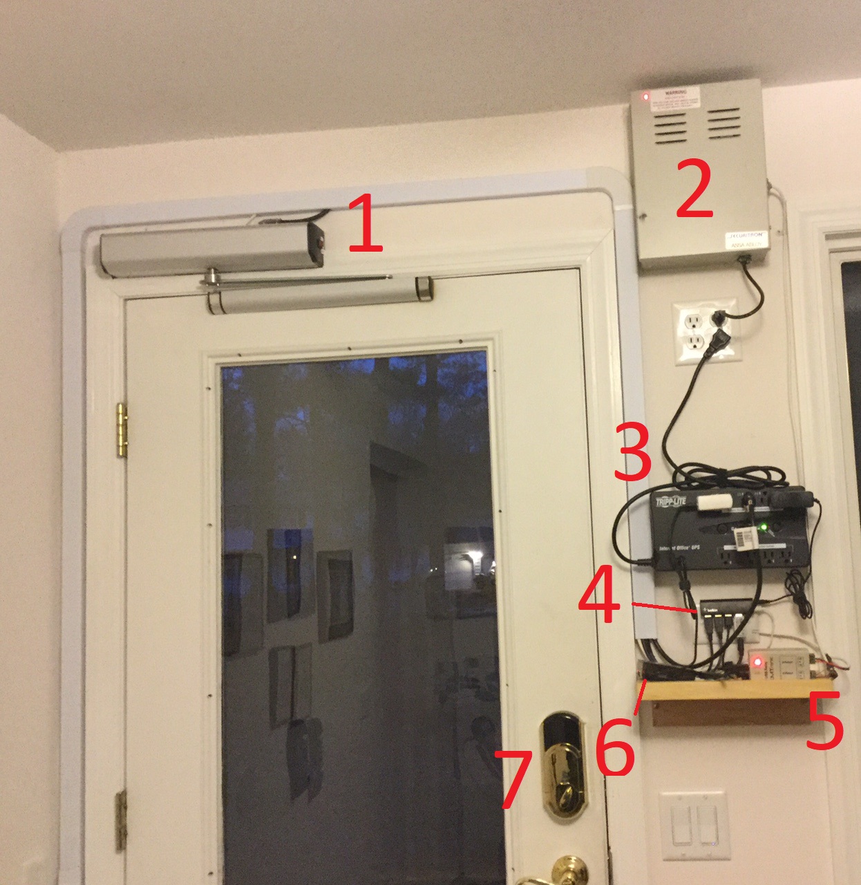
- Door Operator
- 24V DC Power Supply
- Uninterrupted Power Supply
- USB HUb
- USB Relay Box
- Raspberry Pi
- Door lock
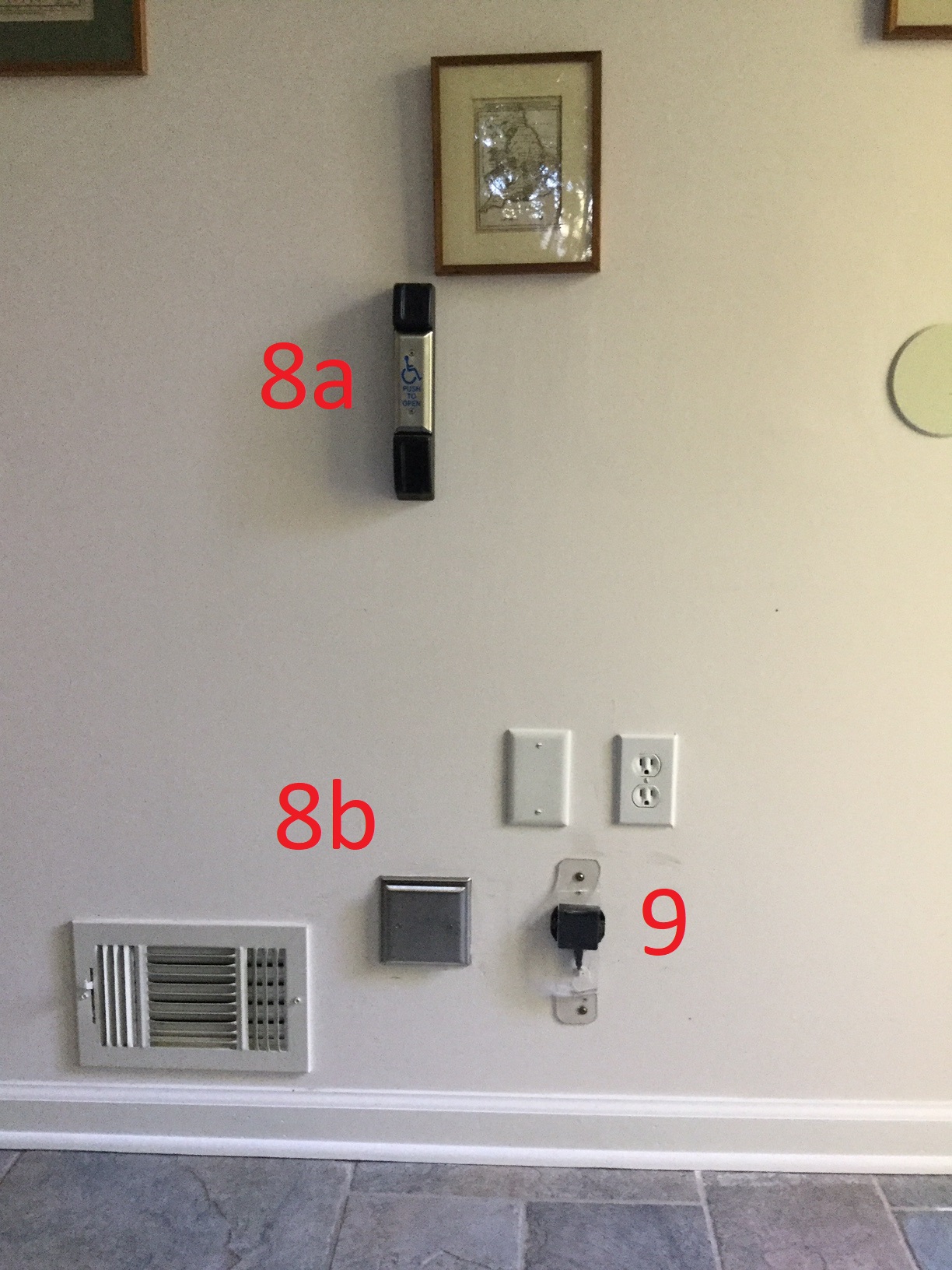
- Upper and lower pushplates
- RFID reader
This same setup is also on the outside of Dr. Ogg's house.
This file is part of DoorOpener. DoorOpener is free software: you can redistribute it and/or modify it under the terms of the GNU General Public License as published by the Free Software Foundation, either version 3 of the License, or (at your option) any later version.
DoorOpener is distributed in the hope that it will be useful, but WITHOUT ANY WARRANTY; without even the implied warranty of MERCHANTABILITY or FITNESS FOR A PARTICULAR PURPOSE. See the GNU General Public License for more details.
You should have received a copy of the GNU General Public License along with DoorOpener. If not, see http://www.gnu.org/licenses/.