Wiring Guide
This section provides detailed instructions on how to wire an LCD display and an I2S amplifier to a Raspberry Pi, along with steps to calibrate the touchscreen and fine-tune the display. It assumes you are using an SPI-based LCD screen and an I2S amplifier for audio output.
To wire the LCD display to your Raspberry Pi, use the following pinout configuration:
| LCD Pin | Raspberry Pi GPIO Pin | Description |
|---|---|---|
| 1, 17 | 3.3V (Pin 1 or 17) | 3.3V power supply. |
| 2, 4 | 5V (Pin 2 or 4) | 5V power supply for the backlight (if required). |
| 6, 9, 14, 20, 25 | GND (Pin 6, 9, etc.) | Ground connections. |
| 11 | GPIO17 (Pin 11) | Touch IRQ (optional, for touch input). |
| 18 | GPIO24 (Pin 18) | LCD Register Select (DC/RS). |
| 19 | GPIO10 (Pin 19, SPI MOSI) | SPI MOSI (data sent to the LCD). |
| 21 | GPIO9 (Pin 21, SPI MISO) | SPI MISO (data received from touchscreen). |
| 22 | GPIO25 (Pin 22) | LCD Reset pin. |
| 23 | GPIO11 (Pin 23, SPI SCLK) | SPI Clock for LCD and touchscreen. |
| 24 | GPIO8 (Pin 24, SPI CE0) | SPI Chip Select for LCD. |
| 26 | GPIO7 (Pin 26, SPI CE1) | SPI Chip Select for touchscreen. |
For audio output, connect an I2S amplifier to the Raspberry Pi’s I2S (PCM) pins as follows:
| Raspberry Pi Pin | GPIO Pin | Function | Connect to Amplifier |
|---|---|---|---|
| Pin 12 | GPIO18 | I2S Bit Clock (BCLK) | BCLK |
| Pin 35 | GPIO19 | I2S Left/Right Clock (LRCLK) | LRCLK |
| Pin 40 | GPIO21 | I2S Data Out (DOUT) | DIN (Audio Data Input to Amplifier) |
| Pin 6 | GND | Ground | GND (Amplifier Ground) |
| Pin 2 or 4 | 5V | Power Supply | VIN (Amplifier Power Input) |
Note: Enable the I2S interface on the Raspberry Pi by following the instructions in the Adafruit MAX98357 guide.
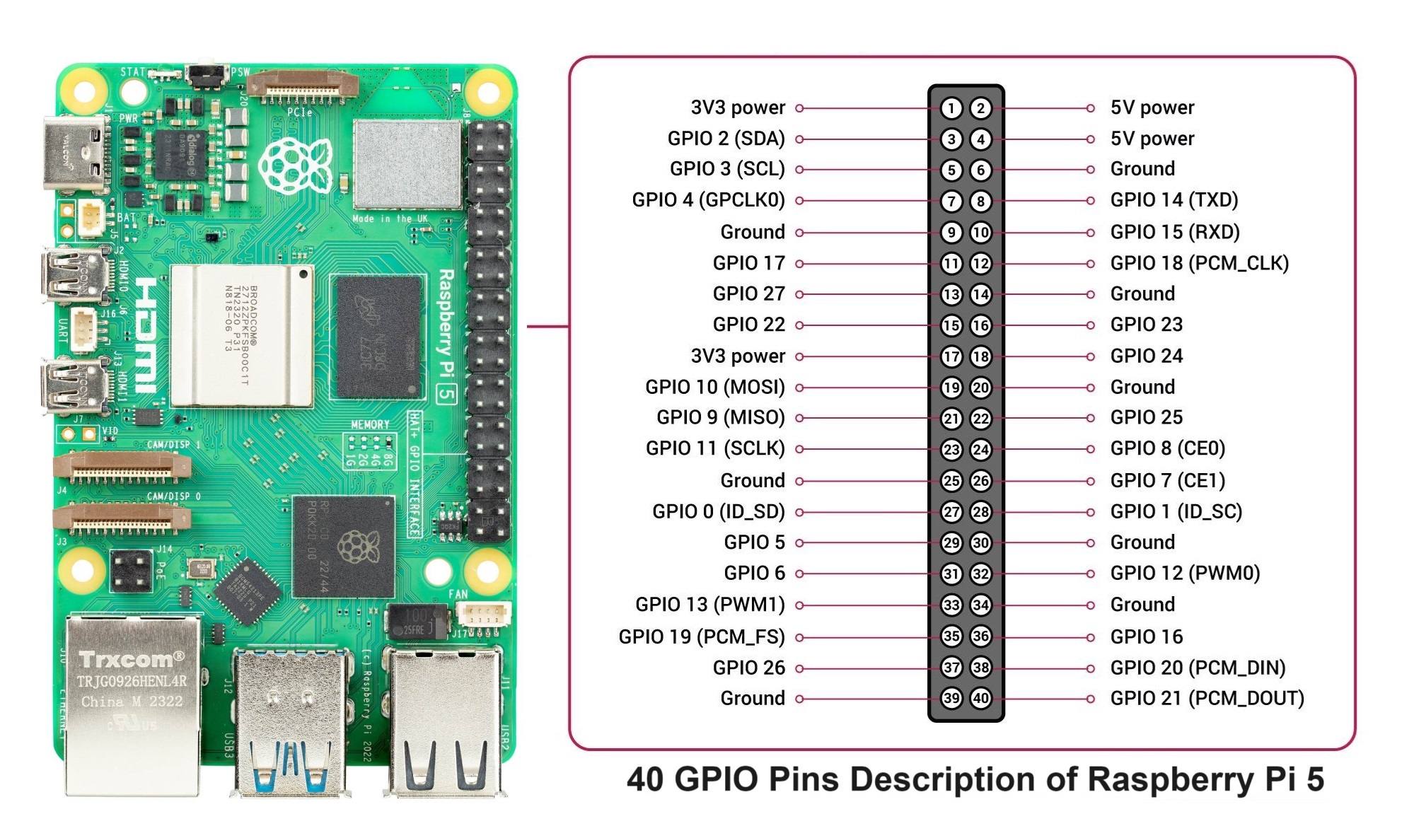
Note: For a comprehensive layout of the Raspberry Pi 5’s GPIO pins, check out the detailed diagram here:
| Controller Pin | Raspberry Pi GPIO Pin | Description |
|---|---|---|
| GND | GND (Pin 6, etc.) | Ground connection. |
| SCL | SCL (Pin 5) | Serial Clock Line for I2C communication. |
| SDA | SDA (Pin 3) | Serial Data Line for I2C communication. |
| VCC | 3.3V (Pin 1 or 17) | Power for the I2C logic. |
Note: Ensure I2C is enabled on your Raspberry Pi using raspi-config. If you need help setting that up, let me know!