- PCBs
- Power Supply
- Chassis
- Front Panel Board
- CPU Board
- DBB & Output Board
- Input Board
- Memory Expansion Board
- 4K RAM Board
- 4K ROM Board
- TTY Interface Board
- Cassette Interface Boards
- Keyboard Interface Board
- Datanetics Keyboard
- SCELBI Keyboard
- Video Board
The SCELBI Minicomputer is considered to be the first general purpose computer to be offered to the general public.
Reference the SCELBI Computer Museum website for documentation, images and software related to the SCELBI computer.
Note on parts: Unless specified, all resistors are 1/4W.
The PCBs were re-created by tracing the original PCBs in KiCAD. PCB sets are available at www.kalinchuk.com. Additional RAM boards and other I/O boards are also available at www.kalinchuk.com.
Coming soon
The front panel is available at www.kalinchuk.com.
If you would like to make your own front panel, you can upload the CAD file to PCBWay and have them fabricate it for you.

The SCELBI requires a +5V power supply and a -12V power supply. The +5V line requires a maximum 1.5A with just the basic boards installed and no memory. The -9V line requires 100mA. The 8H uses 1K RAM boards and each one requires an additional 200mA on both the +5V and -9V lines. Because we're building an 8B SCELBI, the 4K RAM boards do not use -9V so we just need an additional 600mA on the +5 line for each RAM board that we have installed. The 8B also has a memory expansion board (750mA on +5V) and a ROM board (1.5A on +5V and 1.5A on -9V).
In summary, a fully stacked SCEBI 8B (without peripherals) requires a maximum of 5.4A on the +5 line and 1.6A on the -9 line. Because we'll be adding additional peripherals, I think it's safe to use a 6A +5 power supply and a 1.7A -12V power supply (adjusted to -9V). I will be using two Power-One power supplies in my case. You can also use a single one such as the Power-One CP131-A.
Basic tools will be required to make holes in the enclosure. I used a 3" hole saw drill bit to drill a hole for the fan. I also used a 1-11/64" chassis key punch to make a hole for the main power connector. This tool is also used to make holes in the main SCELBI enclosure.
| Part | Quantity | Source |
|---|---|---|
| Bud Enclosure (12"x10"x3") | 1 | Bud Industries AC-413 |
| +5 6A Power Supply | 1 | Power-One C5-6 |
| -12 1.7A Power Supply | 1 | Power-One HB12 |
| 120V Fan | 1 | Qualtek FAA1-08025NBMT31 |
| Fan Guard | 1 | Qualtek 09080-G |
| Red Binding Post | 2 | DigiKey |
| Black Binding Post | 1 | DigiKey |
| Amphenol Connector | 1 | Amphenol 78-S4 |
| Fuse Holder | 1 | Littelfuse Inc. 82000000005 |
| 750mA to 1A Fuse | 1 | SCHURTER Inc. 0034.3773 |
| Power Switch | 1 | NKK Switches S1AWB |
| Cable Gland | 1 | Large enough to fit power cord |
| Lamp Holder | 2 | Holders for lamps (Amazon) |
| Lamp | 2 | Any 5V lamp or LED will do |
| Rubber feet | 4 | DigiKey |
| Power Cord | 1 | A standard computer power cable |
| Wire | N/A | 14AWG wire (~2ft) & 18AWG wire (~5ft) |
| Hardware | N/A | Bolts to mount power supplies and fan |
Refer to the YouTube video for detailed assembly instructions.
Important: The 12V power supply R13 needs to be replaced with a 2W 4700K - 10K resistor. This will allow the voltage to be adjusted to the desired 9V. Also, for the 12V power supply, connect the + terminal to the ground binding post and the - terminal to the -9V binding post.
Follow the following wiring diagram when wiring up the power supply. Also, connect Earth to common ground. Be careful when working with high voltage lines.


The SCELBI 8B chassis was 12" x 10" x 3-1/2" plus the front panel. I have not found a chassis with those dimensions yet although you can get one custom made. The closest chassis that is on the open market is BUD AC-413 which is 12" x 10" x 3" - it works quite well.
Below you will find a list of files that you might find helpful in the construction of the chassis.
Labels (Use StickyLife to print)
The following tools will be required for the assembly of the chassis:
| Tool | Purpose |
|---|---|
| Rotary Dremel | Cutting out the holes for the backplane |
| Drill & Bits | Drilling holes for switches and screws |
| 1-11/64" Chassis Key Punch | Punching out holes for the I/O and power ports |
| Soldering Equipment | Soldering connectors and wires |
These are the parts that I used. Feel free to use the same or go with something else.
| Part | Quantity | Source |
|---|---|---|
| Bud Enclosure (12"x10"x3") | 1 | Bud Industries AC-413 |
| Edge Connectors | 18 | EDAC 305-044-520-202 |
| Card Guides | 18 | Vector Electronics BR27D (comes in set of 2 so only 9 needed) |
| Push Buttons | 3 | E-Switch PS1024ARED |
| Toggle Switches | 8 | CIT Relay and Switch ANT11SEBQE |
| Amphenol 78-S4 | 1 | eBay |
| Amphenol 78-S11 | 14 | eBay |
| Amphenol 86-CP4 | 2 | eBay |
| Wrapping Wire | ~ 20-30' | Blue Electronic Wire DM-30-1000 |
| 14 AWG Wire | ~ 3' | Black, Red, Yellow |
| Power Cable | ~ 3' | Belden 8747 |
| Hardware | N/A | Bolts to mount backplane and card edge guides |
Refer to the YouTube video for detailed assembly instructions. Reference the assembly manual for specifics.

The front panel board is the first board in the SCELBI-8B minicomputer set, although it's model number is 1104.
| Part | Quantity | Source |
|---|---|---|
| 74L04 | 2 | eBay |
| 7416 | 3 | Jameco |
| 7475 | 2 | Jameco |
| 14-pin Socket | 5 | Electronic Surplus : AUGAT - 714AG12D |
| 16-pin Socket | 2 | Electronic Surplus : AUGAT - 716AG12D |
| 560 Ohm Resistor | 1 | Jameco |
| 1K Ohm Resistor | 30 | Jameco |
| 5V LED | 29 | Jameco |
| 6.2V Zener | 1 | DigiKey |
| 10 uF Ele. Cap. | 1 | Jameco |
| 0.1 uF Disk Cap. | 2 | Jameco |
| 0.02 uF Disk Cap. | 1 | Jameco |
| 3/8A 8AG Fuse | 1 | eBay |
| Fuse Clip | 2 | DigiKey |
Refer to the YouTube video for detailed assembly instructions. Reference the assembly manual for the parts layout and additional details.
The first version of the front panel board had Z6 pin 8 connected to ground. That trace needs to be cut. This is fixed in later versions.


The CPU board is the brains of the computer. It's the most complex board of the set and requires the most work to assemble and tune. A good oscilloscope, capable of capturing two separate waves simultaneously and measuring the wave frequency, will be required to tune the CPU board.
Refer to the manual for tuning instructions as it has a pretty detailed writeup on it. I think the YouTube video is a good source for tuning instructions as well.
The parts list contains sources of each part but I actually used time-period or higher quality parts for my build. For example, the list contains potential sources of the ICs but I got the J version of each IC which has a ceramic package. The source for those was usually eBay.
| Part | Quantity | Source |
|---|---|---|
| 7400 | 4 | Jameco |
| 7402 | 1 | Jameco |
| 7403 | 2 | eBay |
| 7404 | 4 | Jameco |
| 74L04 | 2 | eBay |
| 7410 | 2 | Jameco |
| 7420 | 1 | Jameco |
| 7442 | 1 | Jameco |
| 7474 | 3 | Jameco |
| 7476 | 1 | Jameco |
| 74121 | 5 | Jameco |
| Intel 8008 | 1 | eBay |
| 14-pin Socket | 25 | Electronic Surplus : AUGAT - 714AG12D |
| 16-pin Socket | 3 | Electronic Surplus : AUGAT - 716AG12D |
| 1K Ohm Resistor | 8 | Jameco |
| 3.3K Ohm Resistor | 9 | Jameco |
| 10K Ohm Resistor | 18 | Jameco |
| 33K Ohm Resistor | 1 | Jameco |
| 5K Trimpot | 4 | DigiKey |
| 1N914 Diode | 9 | DigiKey |
| 2N2907 Trans. | 1 | DigiKey |
| 10 uF Ele. Cap. | 1 | Jameco |
| 0.1 uF Disk Cap. | 7 | Jameco |
| 0.02 uF Disk Cap. | 1 | Jameco |
| 330 pF Disk Cap. | 4 | Jameco |
| 6.2V Zener | 1 | DigiKey |
| 12.0V Zener (NTE5127A) | 1 | eBay |
| 3/4A 8AG Fuse | 1 | eBay |
| 1/8A 8AG Fuse | 1 | eBay |
| Fuse Clip | 4 | DigiKey |
Refer to the YouTube video for detailed assembly instructions. Reference the assembly manual for the parts layout and additional details.

The DBB & Output board controls the flow of data out of the computer. The board buffers data going out and then strobes the strobe line, for the specific output port, when data is ready to be released.
The parts list contains sources of each part but I actually used time-period or higher quality parts for my build. For example, the list contains potential sources of the ICs but I got the J version of each IC which has a ceramic package. The source for those was usually eBay.
| Part | Quantity | Source |
|---|---|---|
| 7400 | 2 | Jameco |
| 7402 | 4 | Jameco |
| 7416 | 2 | Jameco |
| 7417 | 2 | Jameco |
| 7442 | 4 | Jameco |
| 7475 | 4 | Jameco |
| 14-pin Socket | 10 | Electronic Surplus : AUGAT - 714AG12D |
| 16-pin Socket | 8 | Electronic Surplus : AUGAT - 716AG12D |
| 1K Ohm Resistor | 54 | Jameco |
| 10 uF Ele. Cap. | 1 | Jameco |
| 0.1 uF Disk Cap. | 3 | Jameco |
| 0.02 uF Disk Cap. | 2 | Jameco |
| 6.2V Zener | 1 | DigiKey |
| 1A 8AG Fuse | 1 | eBay |
| Fuse Clip | 2 | DigiKey |
Refer to the YouTube video for detailed assembly instructions. Reference the assembly manual for the parts layout and additional details.
There appears to be a bug in the DBB & Output card. The trace that connects R33, R30, R27, R24, R34, R31, R28, R25 and C4 is the +5 net (according to the schematic) but it's not connected to the +5 trace on the PCB.

The original boards seem to overlook this bug as it appears to be non-critical but I decided to run a jumper wire from that trace to the +5 net.


The input board controls the data coming into the computer and uses multiplexers to select the input port to read.
| Part | Quantity | Source |
|---|---|---|
| 7400 | 1 | Jameco |
| 7404 | 1 | Jameco |
| 7410 | 1 | Jameco |
| 74151 | 8 | Jameco |
| 10K Ohm Resistor | 65 | Jameco |
| 10 uF Ele. Cap. | 1 | Jameco |
| 0.1 uF Disk Cap. | 2 | Jameco |
| 0.02 uF Disk Cap. | 2 | Jameco |
| 6.2V Zener | 1 | DigiKey |
| 3/8A 8AG Fuse | 1 | DigiKey |
| Fuse Clip | 2 | DigiKey |
Refer to the YouTube video for detailed assembly instructions. Reference the assembly manual for the parts layout and additional details.

The memory expansion board contains memory address logic for selecting the correct page of memory. This board enables the SCELBI 8B to use up to 16KB of RAM.
| Part | Quantity | Source |
|---|---|---|
| 7417 | 1 | Jameco |
| 7442 | 9 | Jameco |
| 10K Ohm Resistor | 67 | Jameco |
| 10 uF Ele. Cap. | 1 | Jameco |
| 0.1 uF Disk Cap. | 3 | Jameco |
| 6.2V Zener | 1 | DigiKey |
| 1-1/2A 8AG Fuse | 1 | DigiKey |
| Fuse Clip | 2 | DigiKey |
Refer to the YouTube video for detailed assembly instructions. Reference the assembly manual for the parts layout and additional details.

The RAM board supports up to 4KB of memory. The SCELBI-8B will accept up to four of these RAM boards (for a total of 16KB of memory). 12KB of RAM (3 RAM boards) and 4KB of ROM is the typical setup.
| Part | Quantity | Source |
|---|---|---|
| 7400 | 2 | Jameco |
| 7404 | 1 | Jameco |
| 7420 | 2 | Jameco |
| 2102 1K STATIC RAM | 32 (min 8) | ArcadeShop or Jameco |
| 10K Ohm Resistor | 12 | Jameco |
| 10 uF Ele. Cap. | 1 | Jameco |
| 0.1 uF Disk Cap. | 16 | Jameco |
| 6.2V Zener | 1 | DigiKey |
| 1-1/2A 8AG Fuse | 1 | DigiKey |
| Fuse Clip | 2 | DigiKey |
Refer to the YouTube video for detailed assembly instructions. Reference the assembly manual for the parts layout and additional details.

The ROM board supports up to 4KB of ROM chips. The board accepts up to 16 1602 or 1702 PROMs. The SCELBI 8B ROMs that can be used to flash each PROM can be found here.
| Part | Quantity | Source |
|---|---|---|
| 1602 or 1702 PROM | 1-16 | eBay |
| 10 uF Ele. Cap. | 1 | Jameco |
| 0.1 uF Disk Cap. | 16 | Jameco |
| 0.02 uF Disk Cap. | 1 | Jameco |
| 6.2V Zener | 1 | DigiKey |
| 12.0V Zener (NTE5127A) | 1 | eBay |
| 1-1/2A 8AG Fuse | 2 | DigiKey |
| Fuse Clip | 4 | DigiKey |
Refer to the YouTube video for detailed assembly instructions. Reference the assembly manual for the parts layout and additional details.
The SCELBI computer accepts 16 1702 EPROMs which you can download from the SCELBI website. These EPROM Intel HEX files can be programmed to 16 1702 EPROMs and inserted into the ROM board.
I assembled a 1702 EPROM programmer that Martin Eberhard designed. If you're interested in building this programmer, contact Martin at mfeberhard (at) gmail.com. You can also find the latest manual for it here. I used this programmer to program my 1702s with the SCELBI PROM data.


The TTY interface board is used to connect the SCELBI to a teletype. To use this board, the monitor ROMS (60-63), TTY ROM (76) and Cassette ROM (77) will be required.
| Part | Quantity | Source |
|---|---|---|
| 7400 | 2 | Jameco |
| 7475 | 2 | Jameco |
| 120 Ohm Resistor | 1 | Jameco |
| 330 Ohm Resistor | 1 | Jameco |
| 470 Ohm Resistor | 1 | Jameco |
| 1K Ohm Resistor | 4 | Jameco |
| 2K Ohm Resistor | 2 | Jameco |
| 5.6K Ohm Resistor | 1 | Jameco |
| 6.8K Ohm Resistor | 1 | Jameco |
| 10K Ohm Resistor | 2 | DigiKey |
| 10 uF Ele. Cap. | 1 | Jameco |
| 0.1 uF Disk Cap. | 1 | Jameco |
| 0.02 uF Disk Cap. | 1 | Jameco |
| 2N2222 Trans. | 1 | DigiKey |
| 2N2907 Trans. | 2 | DigiKey |
| 1N914 Diode | 1 | DigiKey |
| 6.2V Zener | 1 | DigiKey |
| 12.0V Zener (NTE5127A) | 1 | eBay |
| 3/4A 8AG Fuse | 2 | DigiKey |
| Fuse Clip | 4 | DigiKey |
| Rubber Feet | 4 | DigiKey |
| Enclosure | 1 | DigiKey |
| 22-Pin Edge Connector | 1 | DigiKey |
| Bracket | 2 | DigiKey |
| Amphenol 78-S11 | 1 | eBay |
| Amphenol 86-CP11 | 3 | eBay |
| Red Binding Post | 2 | DigiKey |
| Black Binding Post | 1 | DigiKey |
| Hardware | N/A | Screws, bolts, etc. |
| Edge Connection | External Connection |
|---|---|
| A-A | +5V |
| A-C | GND |
| A-E | -9V |
| A-K | S1-11 |
| A-L | S1-3 |
| A-M | S1-1 |
| A-N | S1-7 |
| A-P | S1-9 |
| A-R | P3-8 |
| A-V | P2-9 |
| A-W | P2-1 |
| A-X | P1-1 |
| A-Y | P1-9 |
| A-Z | S1-5 |
Refer to the YouTube video for detailed assembly instructions. Reference the assembly manual for the parts layout and additional details.
Because of the way the SCELBI software sends and receives data bits (bit banging), it's possible to convert the bits to serial using a simple latch and a serial tranceiver (MAX232). You can find the schematics for a SCELBI serial interface and the Gerber file for the PCB here.
The nice thing about the above serial board is that it's a direct replacement of the TTY board. In my build, I actually have both the TTY board and the serial board in one enclosure with a switch to toggle between TTY and serial. The switch just toggles the power for each board. It works quite well.


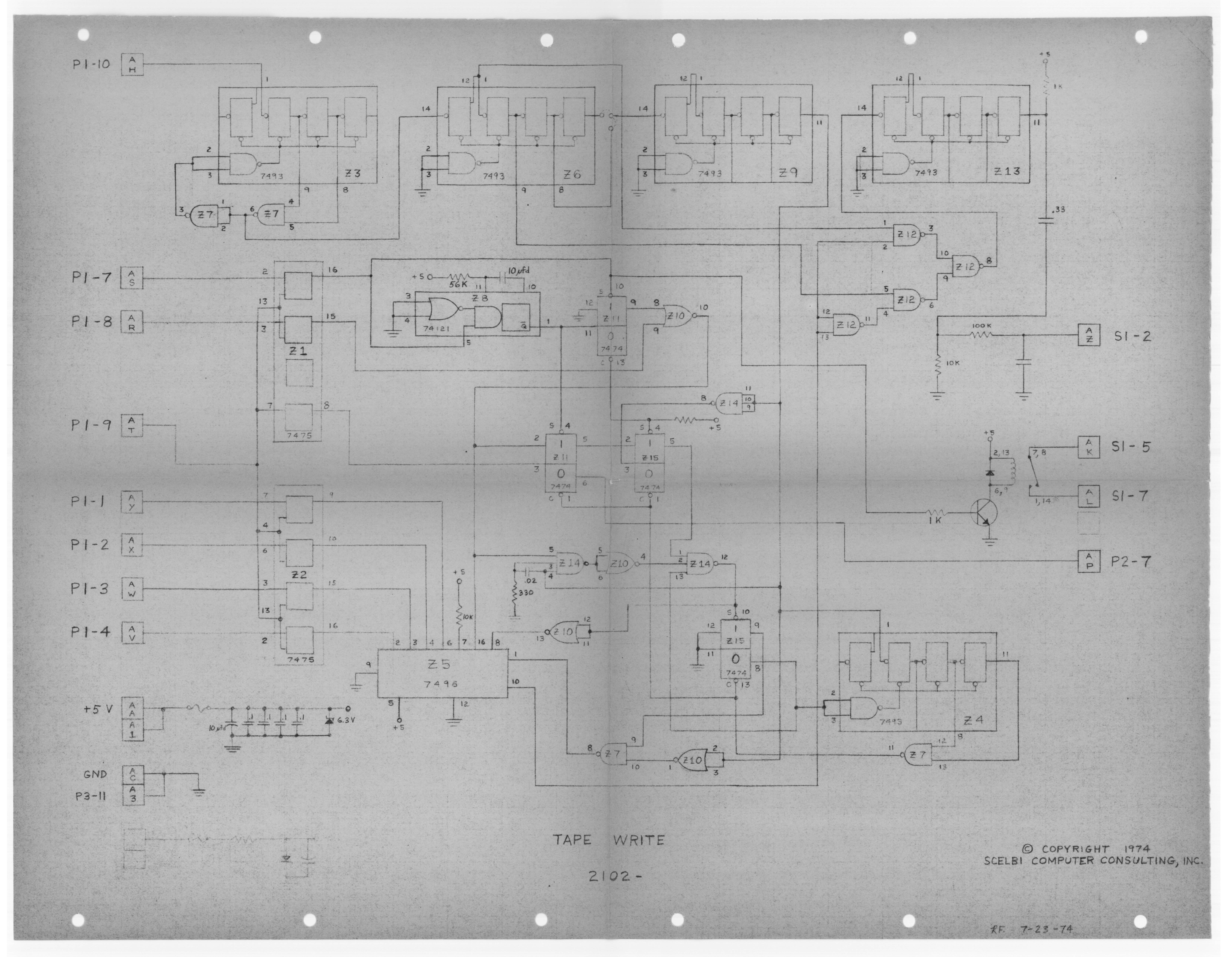
The TTY cassette interface boards are used to connect the SCELBI to a tape reader. One board is used to write data from the SCELBI and the other is used to read data into the SCELBI. To use this interface, the monitor ROMS (60-63) and Cassette ROM (77) will be required. If you're using the TTY interface, you'll also need TTY ROM (76). The ROMs can be found here.
The following parts are required for the enclosure. Parts for individual boards are listed below. You can find the parts layout in the manual that Mike Willegal created here.
| Part | Quantity | Source |
|---|---|---|
| Rubber Feet | 4 | DigiKey |
| Enclosure | 1 | DigiKey |
| 22-Pin Edge Connector | 2 | DigiKey |
| Bracket | 2 | DigiKey |
| Amphenol 78-S11 | 1 | eBay |
| Amphenol 86-CP11 | 2 | eBay |
| Red Binding Post | 1 | DigiKey |
| Black Binding Post | 1 | DigiKey |
| Hardware | N/A | Screws, bolts, etc. |
I also used a block of wood to hold the boards in place at the other end of the edge connectors.

| Part | Quantity | Source |
|---|---|---|
| 7400 | 2 | Jameco |
| 7475 | 2 | Jameco |
| 7474 | 2 | Jameco |
| 7410 | 1 | Jameco |
| 7402 | 1 | Jameco |
| 74121 | 1 | Jameco |
| 7496 | 1 | eBay |
| 7493A | 5 | eBay |
| W117DIP-1 (relay) | 1 | eBay |
| 330 Ohm Resistor | 1 | Jameco |
| 1K Ohm Resistor | 2 | Jameco |
| 10K Ohm Resistor | 3 | DigiKey |
| 47K Ohm Resistor | 1 | Jameco |
| 100K Ohm Resistor | 1 | Jameco |
| 10 uF Ele. Cap. | 2 | Jameco |
| 0.1 uF Disk Cap. | 6 | Jameco |
| 0.02 uF Disk Cap. | 1 | Jameco |
| 0.47 uF Ele. Cap. | 1 | eBay |
| 2N2222 Trans. | 1 | DigiKey |
| 1N4148 Diode | 1 | Jameco |
| 6.2V Zener | 1 | DigiKey |
| 3/4A 8AG Fuse | 1 | DigiKey |
| Fuse Clip | 2 | DigiKey |
Note that 0.33 uF capacitor is excluded even though there is a footprint for it on the PCB.
| Part | Quantity | Source |
|---|---|---|
| 7400 | 1 | Jameco |
| 7404 | 1 | Jameco |
| 74121 | 1 | Jameco |
| 72741 | 2 | eBay |
| 560 Ohm Resistor | 2 | Jameco |
| 1K Ohm Resistor | 4 | Jameco |
| 2.2K Ohm Resistor | 1 | Jameco |
| 2.7K Ohm Resistor | 1 | Jameco |
| 3.9K Ohm Resistor | 1 | Jameco |
| 8.2K Ohm Resistor | 1 | Jameco |
| 10K Ohm Resistor | 7 | DigiKey |
| 22K Ohm Resistor | 2 | Jameco |
| 33K (~30K) Ohm Resistor | 1 | Jameco |
| 100K Ohm Resistor | 1 | Jameco |
| 10K Trimpot | 1 | DigiKey |
| 10 uF Ele. Cap. | 2 | Jameco |
| 0.1 uF Disk Cap. | 3 | Jameco |
| 330 pF Disk Cap. | 1 | Jameco |
| 0.02 uF Disk Cap. | 3 | Jameco |
| 0.01 uF Film Cap. | 2 | eBay |
| 0.0068 uF Film Cap. | 1 | eBay |
| 0.1 uF Film Cap. | 3 | eBay |
| 0.047 uF Filk Cap. | 1 | eBay |
| 2N2222 Trans. | 2 | DigiKey |
| 2N2907 Trans. | 2 | DigiKey |
| 5V LED | 1 | Jameco |
| 1N4148 Diode | 4 | Jameco |
| 6.2V Zener | 1 | DigiKey |
| 3/4A 8AG Fuse | 1 | DigiKey |
| Fuse Clip | 2 | DigiKey |
Since there are two separate boards, there will be two edge connectors in the enclosure. The write board goes on the bottom and the read board goes on top. Wire up each edge connector to the external connections as outlined below.

| Edge Connection | External Connection | Notes |
|---|---|---|
| A-A | +5V | |
| A-C | GND, P3-11 | |
| A-H | P1-10 | |
| A-K | S1-5 | |
| A-L | S1-7 | |
| A-P | P2-7 | |
| A-R | P1-8 | |
| A-S | P1-7 | |
| A-T | P1-9 | |
| A-V | P1-4 | |
| A-W | P1-3 | |
| A-X | P1-2 | |
| A-Y | P1-1 | |
| A-Z | S1-2 | + side of jack; connect - to GND (S1-11) |
| Edge Connection | External Connection | Notes |
|---|---|---|
| A-A | +5V | |
| A-C | GND | |
| A-L | S1-1 | + side of jack |
| A-J | S1-11 | - side of jack |
| A-X | P2-8 | |
| A-Z | P2-10 |
There are three jacks that connect to S1 - two are required and one is optional. S1-1 and S1-11 will connect to the headphone jack (3.5mm). S1-2 and S1-11 will connect to the microphone jack (3.5mm). The optional connection, S1-5 and S1-7, connect to the REM (remote) jack (2.5mm). This remote jack is used to start and stop the cassette when reading/writing.
The GND/- connection will connect to the outside of the jack.

The cassette interface uses ports INP3 and OUT3 (4th port from the right if looking from the top). Those two ports need to have pin 10 connected to the CPU SYNC signal. I don't believe the original assembly instructions specified this connection but the cassette interface boards require the SYNC signal which is expected on pin 10 of connector P1 and P2. The SYNC signal is located on XA02 B-A.

Refer to the YouTube video for detailed assembly instructions. Reference the assembly manual for the parts layout and additional details.
The write board should work without any tuning, other than the microphone input volume on the tape readers side. Mike Willegal noted that the 0.02 uF capacitor, near the 330 ohm resistor, may need to be adjusted to 0.004 uF for proper operation.
The read board will require some tuning by adjusting the 10K trimpot. I adjusted mine to approximately 6K ohm before I got it to read consistently. To make this easier, I drilled a hole in the enclosure, right in front of the trimpot so I could access it with a screw driver. On that note, you might want to drill a hole for the LED if you'd like, since it lights up when data is present during a read operation.
There is one bug on the write that will prevent the board from operating correctly. On the original schematic, Z1 has pin 7 connected to pin 13 (and other pins). Pin 7 of the 7475 is actually a DATA pin but it's treating it as an ENABLE pin since all other connected pins are the ENABLE pins.

This needs to be fixed to pin 6 (not pin 7) as pin 6 is the ENABLE pin. The PCBs that were created based on the schematic have this bug so they will need to be corrected by cutting the trace between pin 7 and pin 13 of Z1 and connecting pin 13 to pin 6 instead. This will be fixed in future PCBs but verify your PCB if you have one.


The KBD interface board is used to connect the SCELBI to a keyboard input. The keyboard is used in conjunction with the oscilloscope board (or a similar form of output). To use this interface, the monitor ROMS (60-63) and KBD/Oscilloscope ROM (76) will be required. The 76 slot is shared with the TTY ROM as well so you can only have either the KBD/Oscilloscope or the TTY ROM in use at the same time. The ROMs can be found here.
The following parts are required for the enclosure. Parts for the PCB are listed below. You can find the parts layout in the manual that Mike Willegal created here.
| Part | Quantity | Source |
|---|---|---|
| Rubber Feet | 4 | DigiKey |
| Enclosure | 1 | DigiKey |
| 22-Pin Edge Connector | 2 | DigiKey |
| Bracket | 2 | DigiKey |
| Amphenol 78-S11 | 1 | eBay |
| Amphenol 86-CP11 | 2 | eBay |
| Red Binding Post | 1 | DigiKey |
| Black Binding Post | 1 | DigiKey |
| Hardware | N/A | Screws, bolts, etc. |
I also used a block of wood to hold the boards in place at the other end of the edge connectors. This is similar to what I did with the cassette interface.
| Part | Quantity | Source |
|---|---|---|
| 7400 | 1 | Jameco |
| 7404 | 2 (4) | Jameco |
| 7475 | 2 | Jameco |
| 7474 | 1 | Jameco |
| 7410 | 1 | Jameco |
| 270 Ohm Resistor | 1 | Jameco |
| 10K Ohm Resistor | 2 | DigiKey |
| 1 uF Ele. Cap. | 2 | Jameco |
| 10 uF Ele. Cap. | 2 | Jameco |
| 0.1 uF Disk Cap. | 2 | Jameco |
| 0.02 uF Disk Cap. | 1 | Jameco |
| 1N4148 Diode | 2 | Jameco |
| 6.2V Zener | 1 | DigiKey |
| 1/5A 8AG Fuse | 1 | DigiKey |
| Fuse Clip | 2 | DigiKey |

| Edge Connection | External Connection |
|---|---|
| A-A | +5V |
| A-B | S1-10 |
| A-C | GND, S1-11, P1-11 |
| A-F | S1-1 |
| A-H | S1-2 |
| A-J | S1-3 |
| A-K | S1-4 |
| A-L | S1-5 |
| A-M | S1-6 |
| A-N | S1-7 |
| A-P | S1-8 |
| A-R | P2-1 |
| A-S | P2-2 |
| A-T | P2-3 |
| A-U | P2-4 |
| A-V | P2-5 |
| A-W | P2-6 |
| A-X | P2-7 |
| A-Y | P2-8 |
| A-Z | P1-9 |
Refer to the YouTube video for detailed assembly instructions. Reference the assembly manual for the parts layout and additional details.

The Datanetics keyboard is a good keyboard to use with the SCELBI computer. This keyboard is used with the Apple I as well. You can find additional details about this keyboard replica at https://github.com/schlae/replica-datanetics.
There are two variants of PCBs available for sale at kalinchuk.com:
Original variant with encoder and original keyswitches
Modern variant with MX keyswitches and microcontroller
I decided to build the modern variant since original key switches can be hard to find.
The parts list can be found here.
Most of the parts can be sourced from many of the online hobby stores or eBay so I won't include them here but you can find key components in the list below.
| Part | Quantity | Source |
|---|---|---|
| ATMEGA644 | 1 | DigiKey |
| Key Caps | 1 Set | FK Caps - modify as needed |
| Space Key Stabilizer | 1 | mechanicalkeyboards.com - this one is 7U so make sure your space key is the same size |
| MX Switches | ~60 | Amazon - 110 quantity |
The ATMEGA644P needs to be programmed in order to work correctly as an encoder for the keyboard. A programmer can be built using basic components and an Arduino. In my case, I used the XGecu T48 programmer to program mine and this route is much simpler. Download the binary file from the GitHub repo and load it into the programmers software. Next, go to the "Config" tab on bottom and select the correct fuses by enabling the checkboxes to get the matching hex:
lfuse = 0x62
hfuse = 0xdd
efuse = 0xfc
Then press "Program". This will program the microcontroller in just a few seconds.
Refer to the YouTube video for detailed assembly instructions.

The SCELBI Monitor Editor Assembler can only support a TTY interface or an oscilloscope/keyboard. The following is the Datanetics keyboard from above inserted into a Hammond 1444-1372 enclosure with an Amphenol connector to connect to the SCELBI Keyboard Interface.
The following parts are required for the enclosure.
| Part | Quantity | Source |
|---|---|---|
| Rubber Feet | 4 | DigiKey |
| Enclosure | 1 | DigiKey |
| Enclosure Bottom | 1 | DigiKey |
| 15-Position 30-Pin Edge Connector | 1 | eBay |
| Amphenol 86-CP11 | 1 | eBay |
| Hardware | N/A | Standoffs, washers, etc. |
The edge connector is optional and the wires can be directly soldered to the PCB.
Refer to the Replica Datanetics GitHub for the connections coming from the keyboard. Then reference the [Keyboard Interface connections] to determine how to wire up the keyboard to the Amphenol connector.
If you're interested in the keyboard stiffener, you can find the fabrication files here. Use these files to upload to PCBWay and PCBWay will make the stiffener for you. Select "sheet metal fabrication" for both the bottom stiffener and end stiffeners.
I could not find the oscilloscope/keyboard ROM on scelbi.com but someone on the VCF Forum posted the Intel Hex and the disassembled source for it which I used in my setup. I'm also including it here for reference - just to make sure it's archived.
Refer to the YouTube video for detailed assembly instructions. Reference the assembly manual for the parts layout and additional details.
Coming soon