Power Module
Caution
This part of the project deals with mains voltage. While this wiring is not complicated, if you are not careful you can kill yourself.
- There will be mains voltage inside the power module when it is operating. The high voltage wiring is pretty simple, but don't skimp on the insulation/heat shrink on the wires and make sure that all the wires are secure and do not contact anything on the AC/DC power supply.
- Also note, there are large capacitors on the AC/DC converter, so even after power is removed, there may be high voltage present on the supply for a few minutes. In general, wait a few minutes after unplugging power before you do anything that might involve inadvertently touching the converter.
- It should also go without saying: Don't do anything inside the power module with high voltage power plugged in.
Attach the wires to the power entry module as shown below.
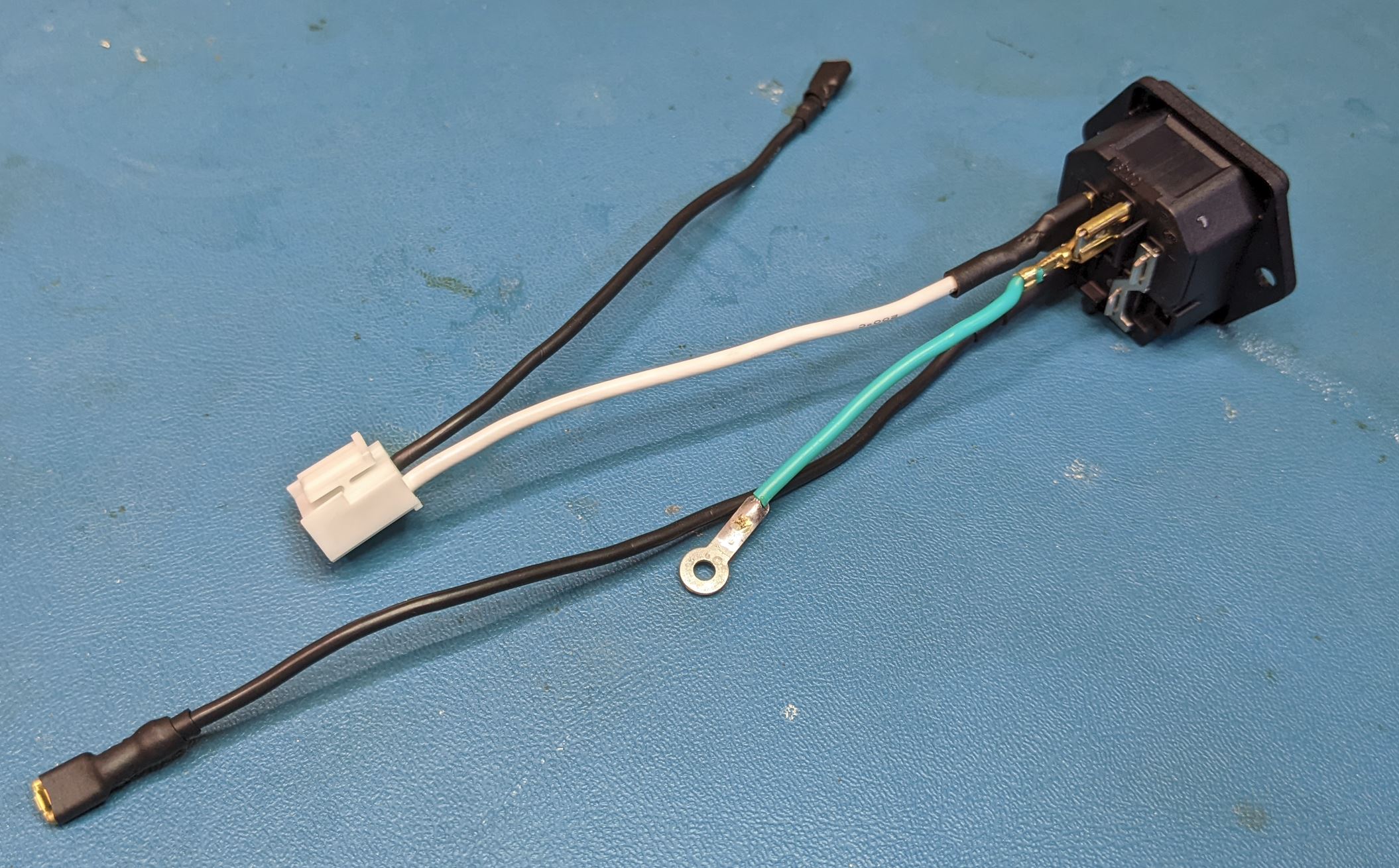
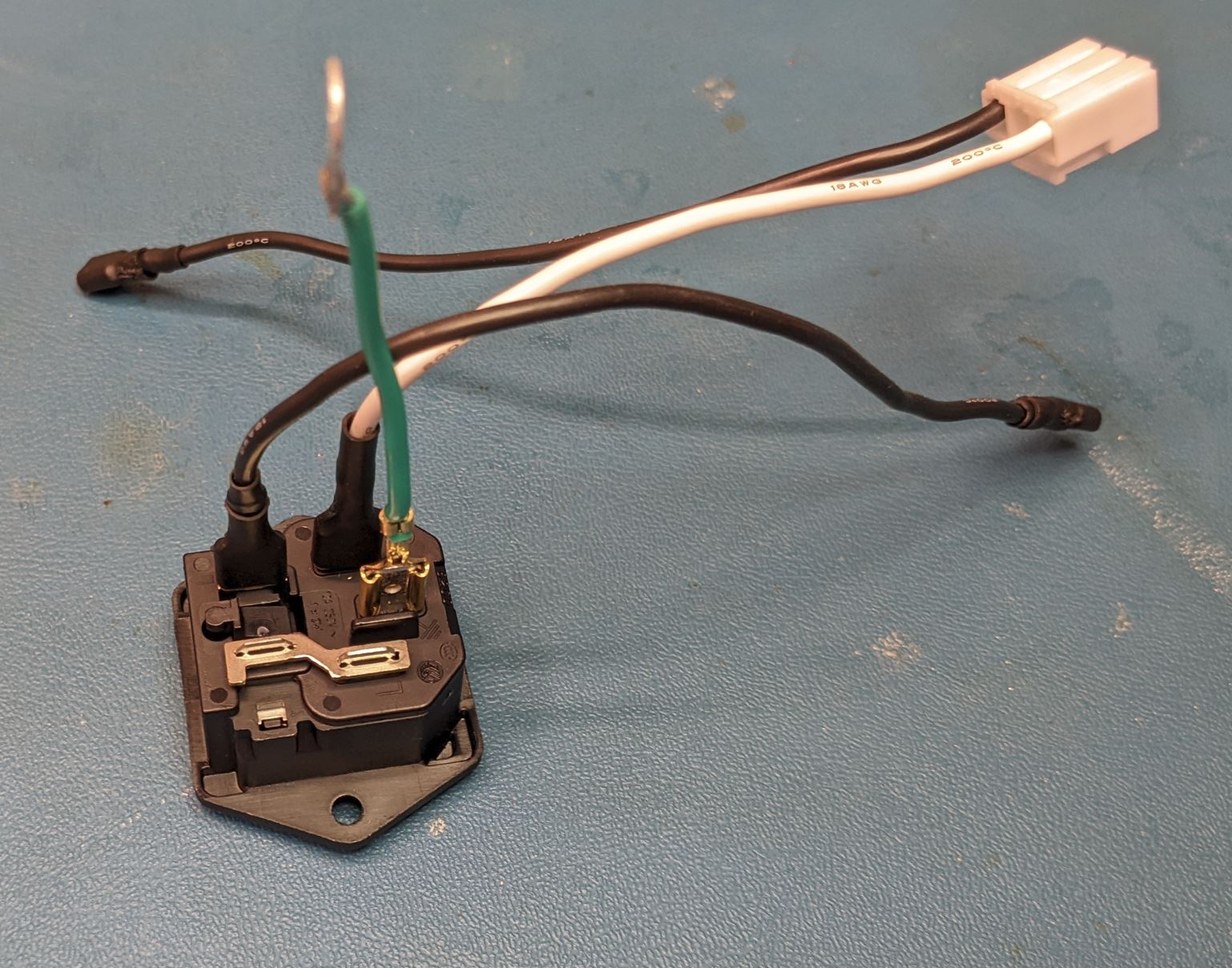
For those unfamiliar with AC wiring, the coloring convention for the wires (in the US, at least) is black for hot (high voltage), white for neutral (return) and green for earth (safety ground).
With the wires attached, slide the power entry module into the back of the power module case and secure with two screws (Self tapping #4 flat head, 3/8" Length).
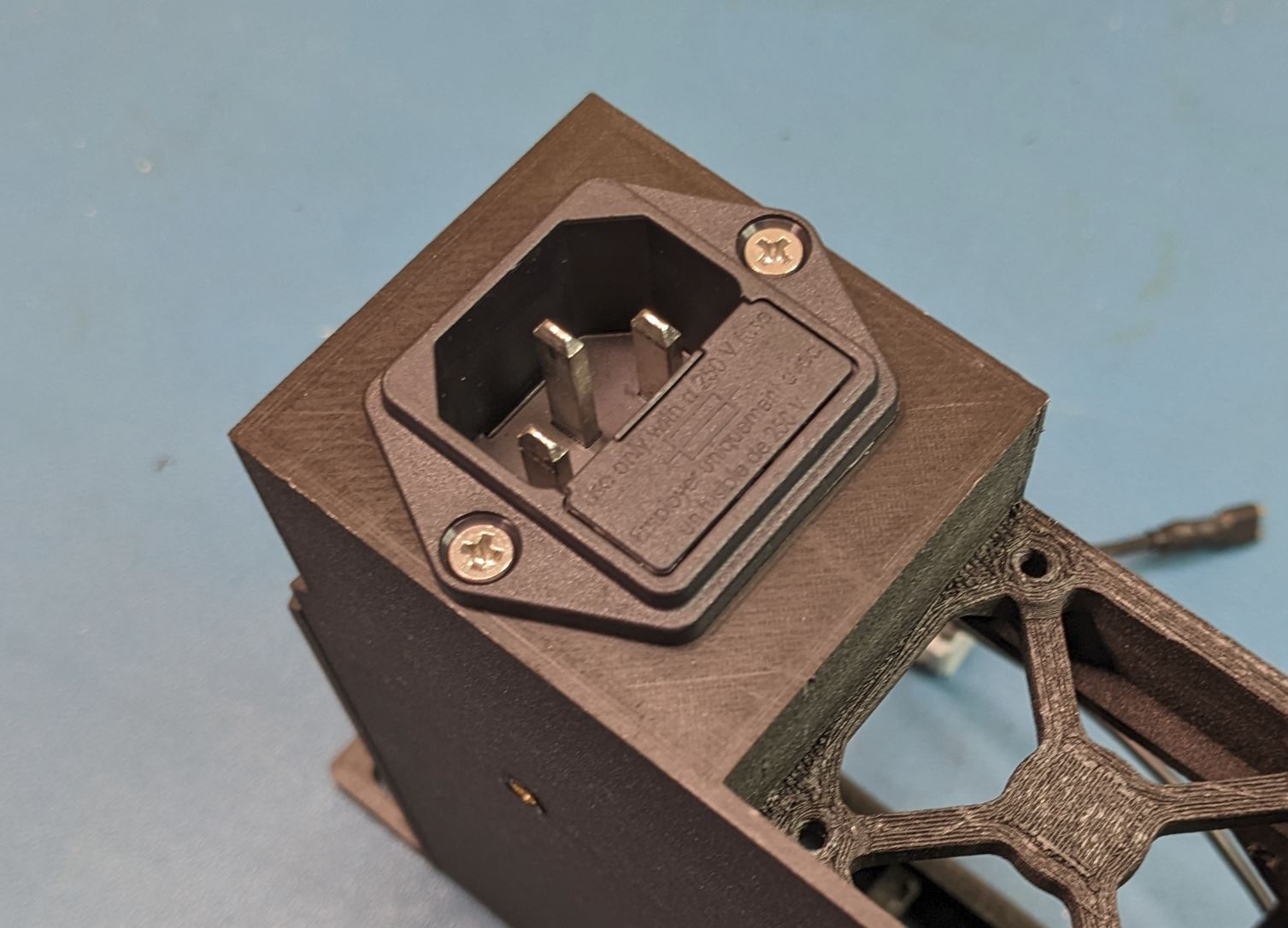
Note that the power entry module can fit in two orientations in the case. Either is okay, but I found the shown orientation worked better for cable routing.
At this step, you can install the fuse into the power entry module. I used a 1A fuse, which should blow at ~120W, way more than the 35W max output of the AC/DC supply. Note in the image below, there are two fuses in the holder. The one towards the end of the fuse holder is a spare.

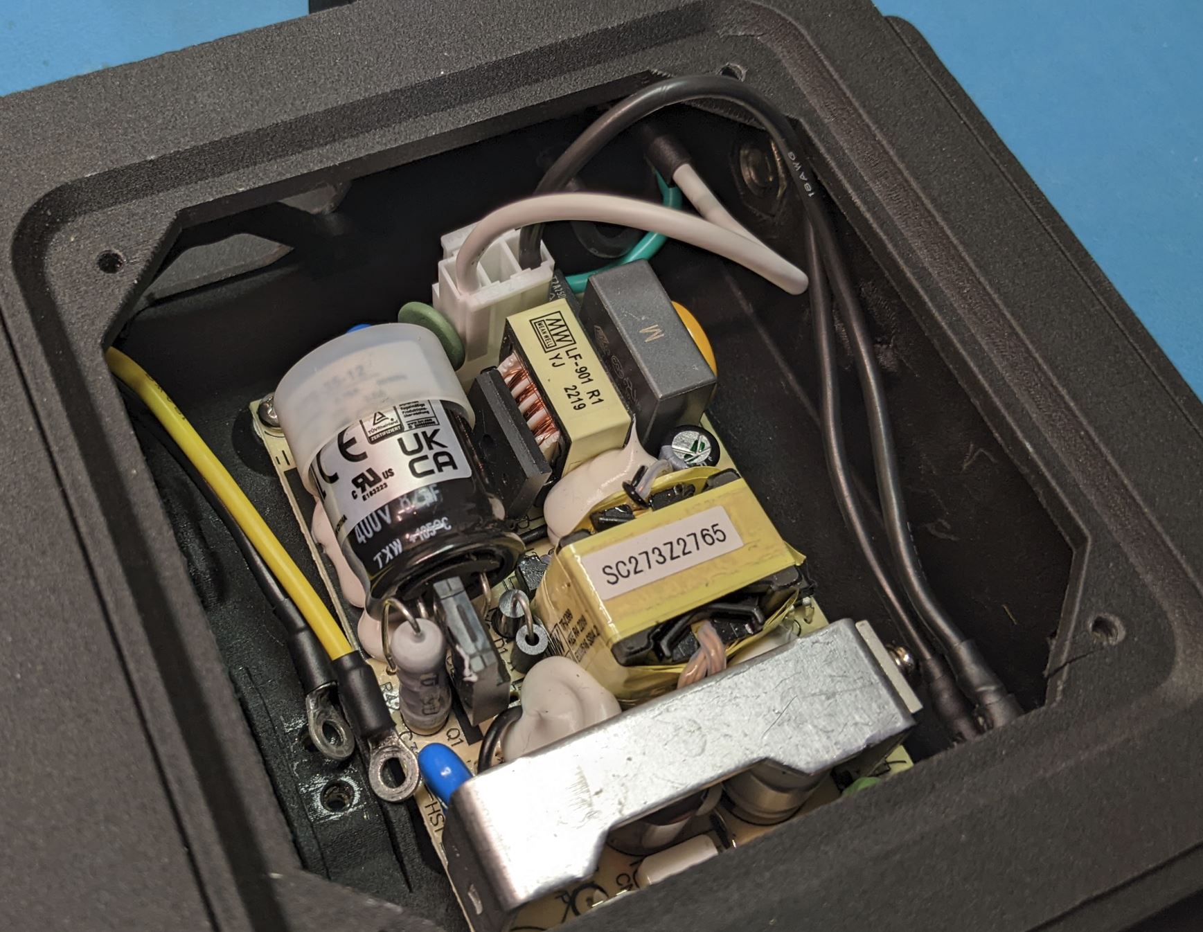
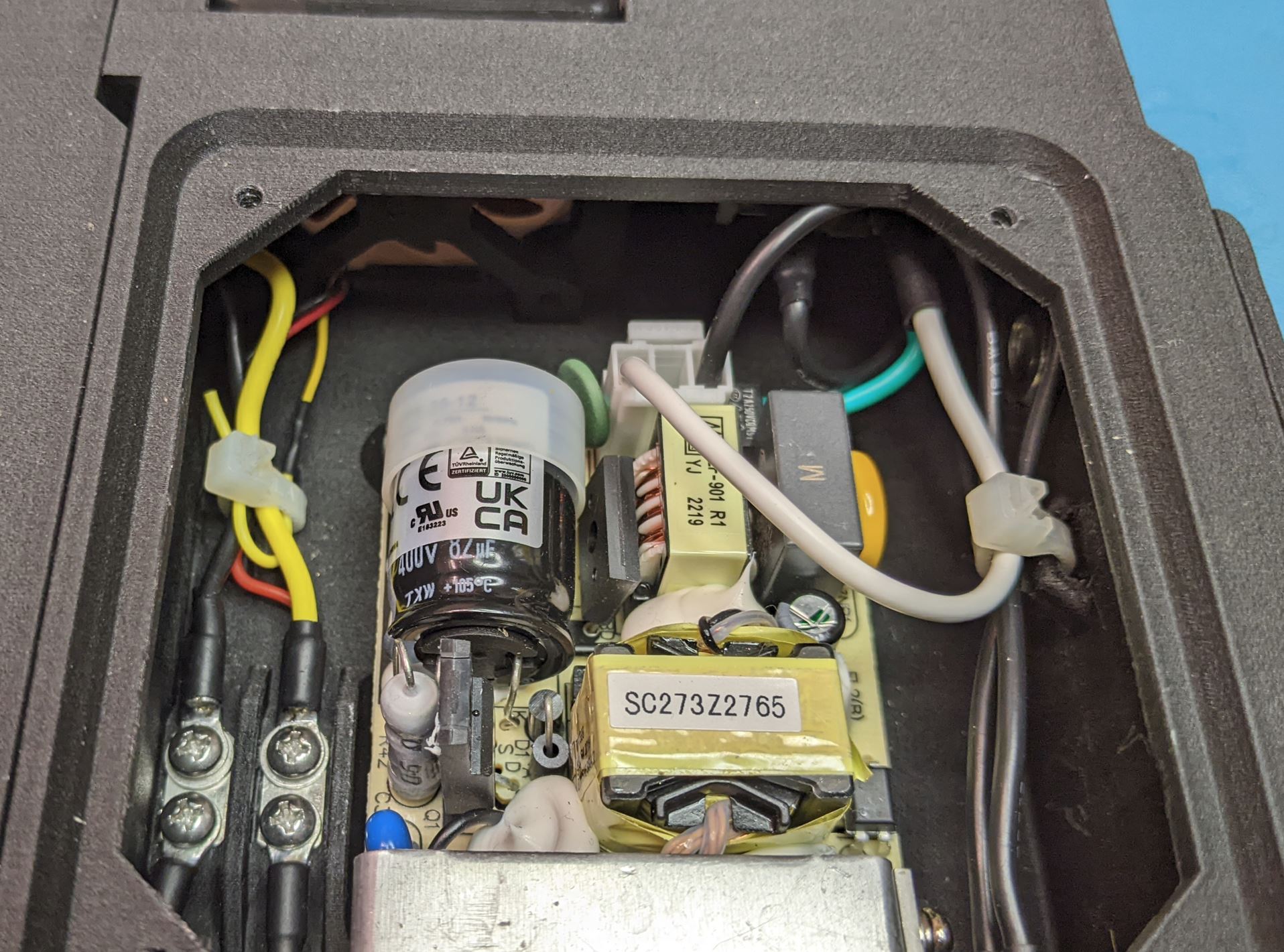
Place the AC/DC converter into the case as shown. The four mounting holes will line up with the four mounting pads in the case. Secure the converter to the case using four #4-40 PHMS (.25" Length). The back left mounting hole also contains contacts for the safety ground. Before installing the screw, slide the safety ground tab between the converter PCB and the pad below it. (This pad is a bit shorter than the rest to account for this).
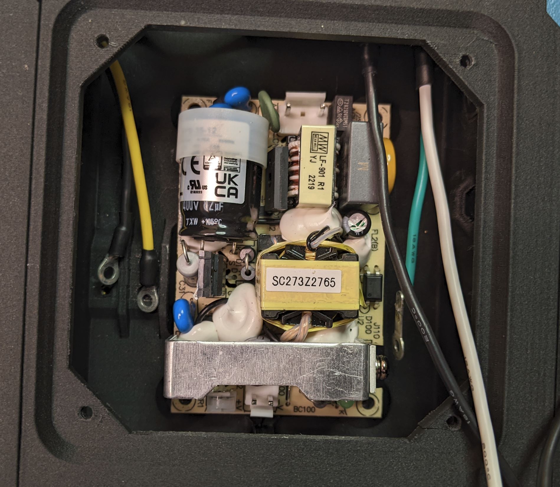
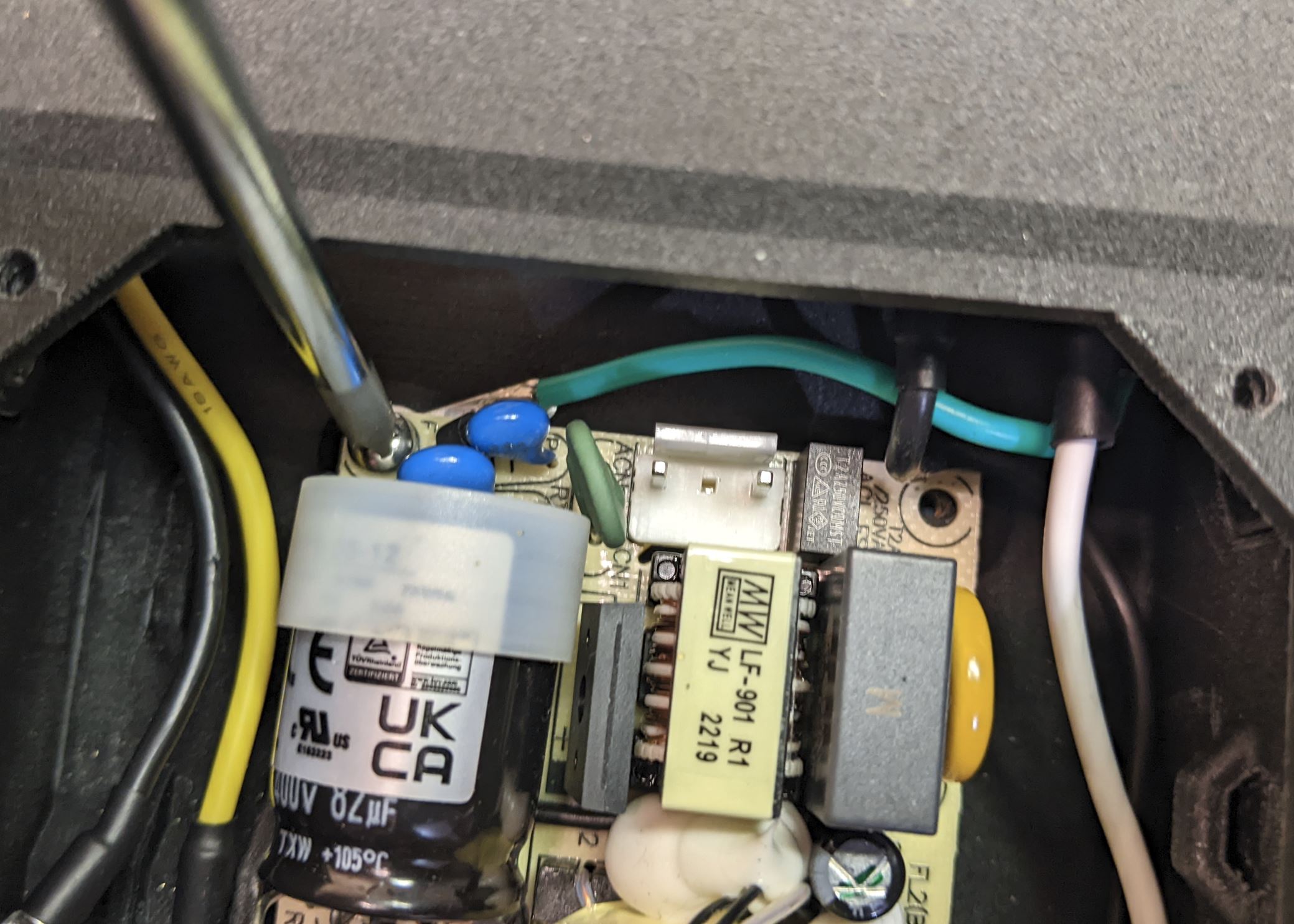
Take note of the two connectors on the board. The AC input connector (the three pin connector with the middle pin missing) should be facing the back of the case.
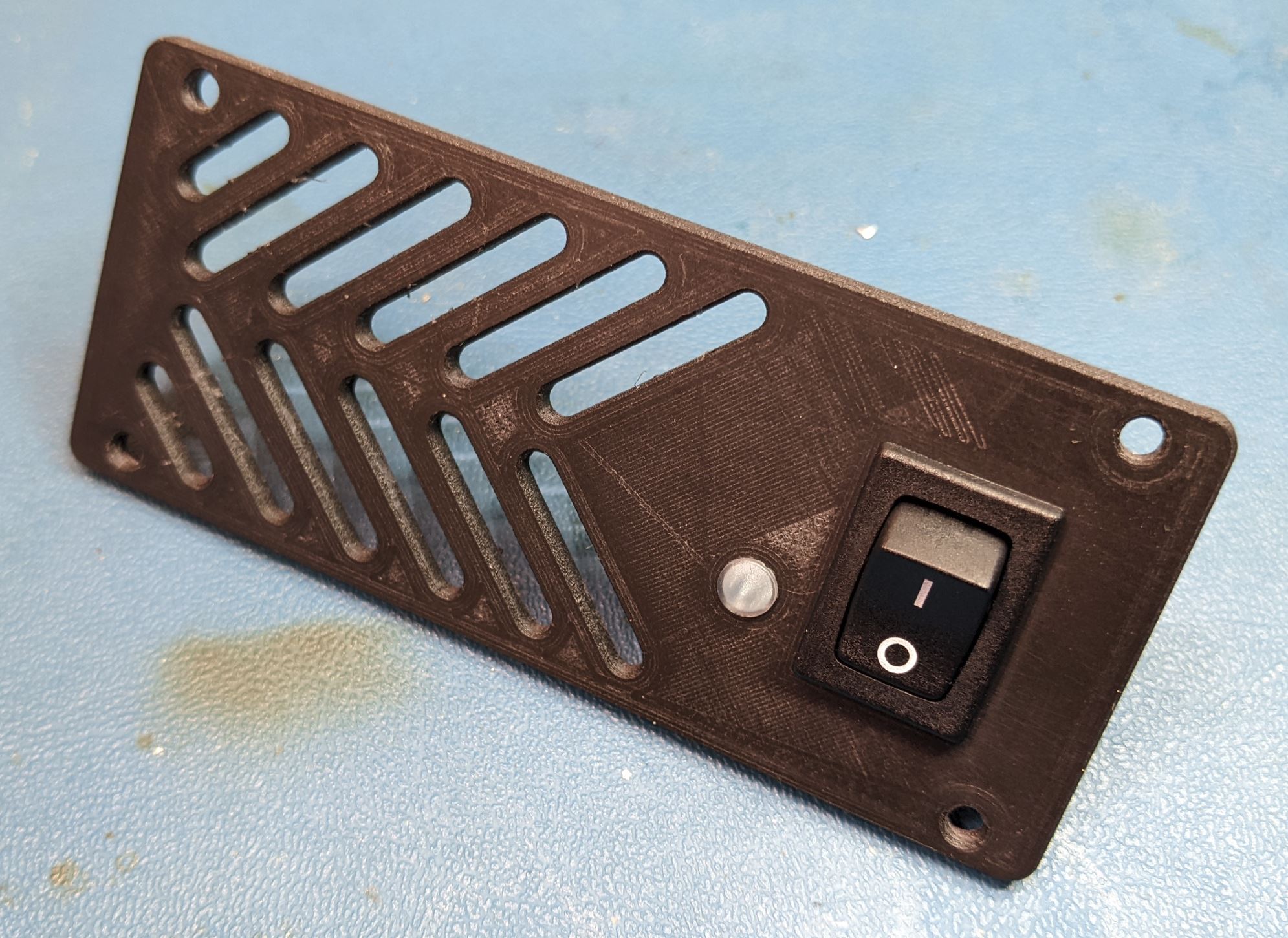
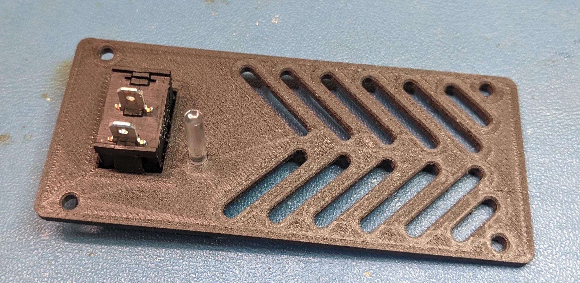
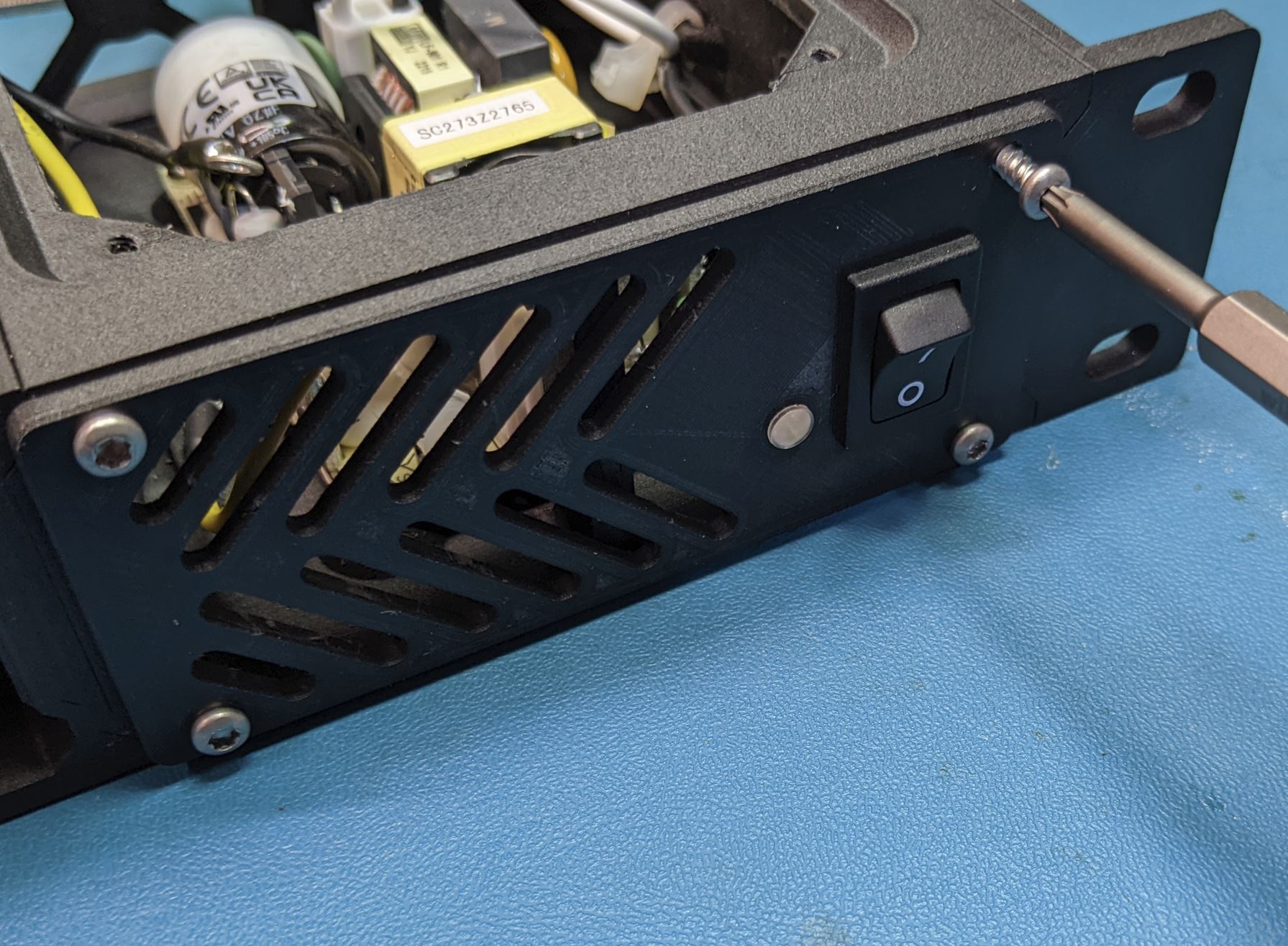
The switch and light pipe both press in from the front side of the front cover as shown. The switch will snap into place, and the light pipe will be a friction fit. You may have to use a knife to widen the hole for the light pipe slightly to make it fit. The small flange on the front of the light pipe should be flush with the front of the cover.
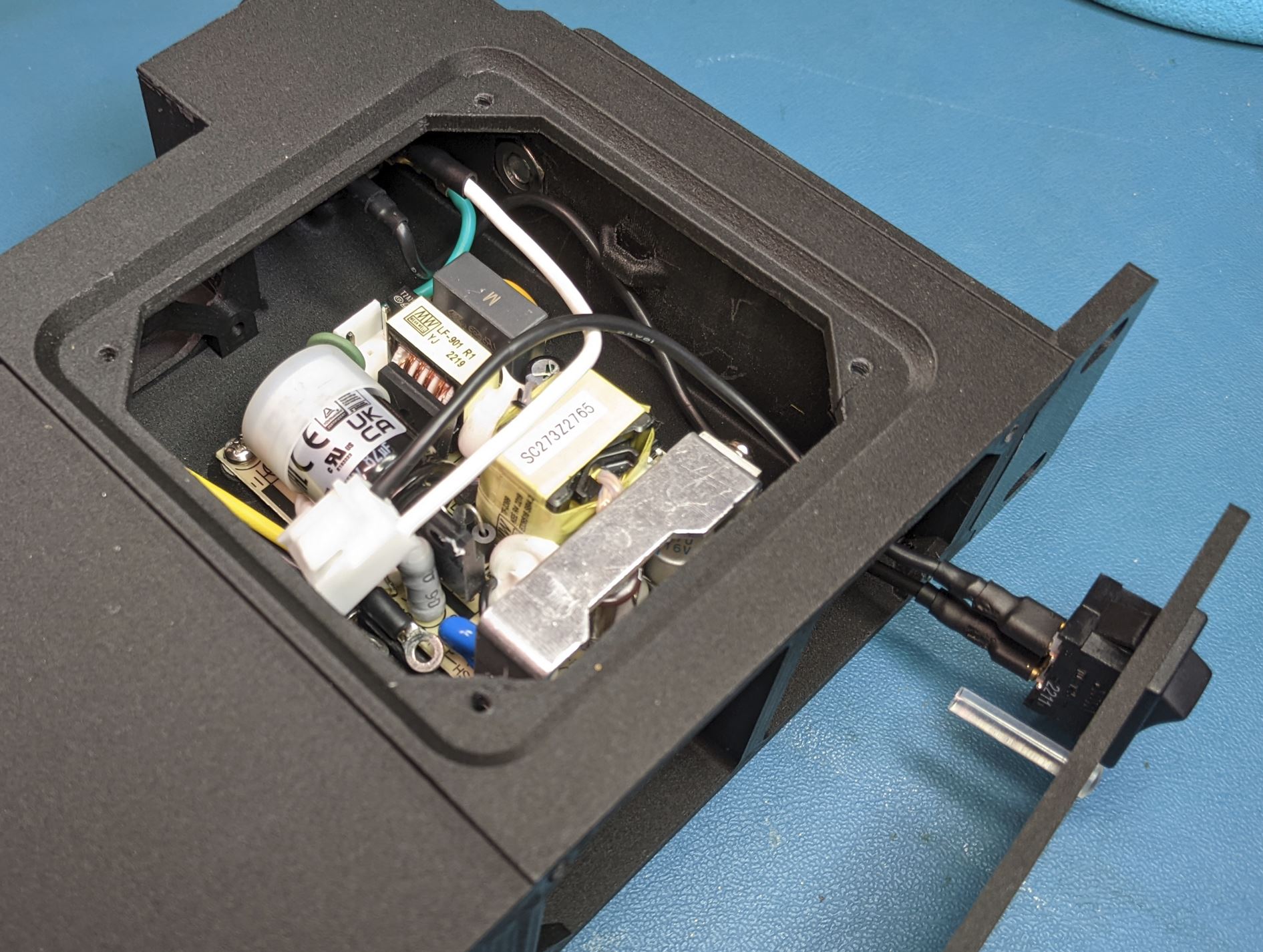
Place the front cover close to its final position and attach the two black wires to the switch. It does not really matter which wire goes to which terminal. Take care at this step to make sure the wires are routed so that they can be separated from the AC/DC converter. You will note in the below image that I routed the hot (black) wire behind the safety ground (green).
After the parts are positioned, screw the front cover to the power module frame with four self tapping pan screws. (#4 size, .5" Length)
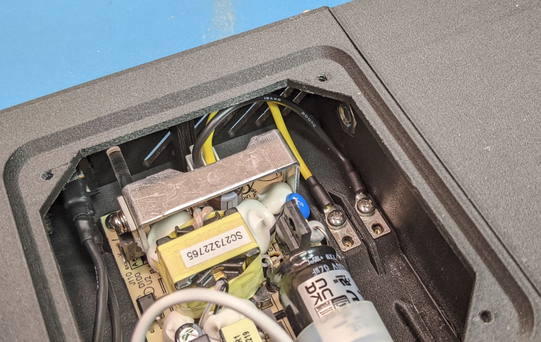
After the front cover is installed, verify that the wires can be routed away from the AC/DC converter and plug the AC connector to the board. Push the connector down until it clicks into place.
plug the white connector on the DC output cable into the DC output socket on the AC/DC converter.
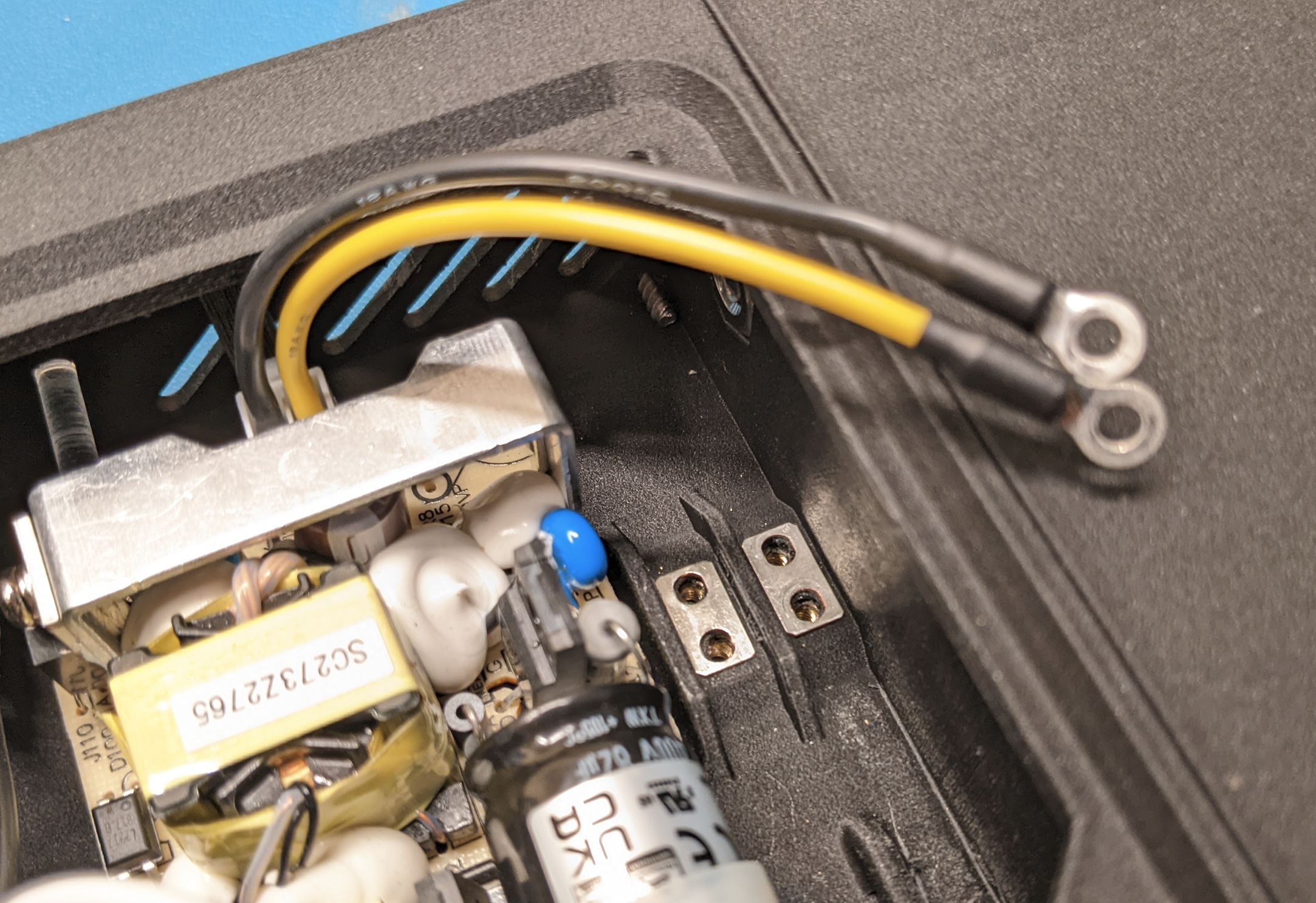
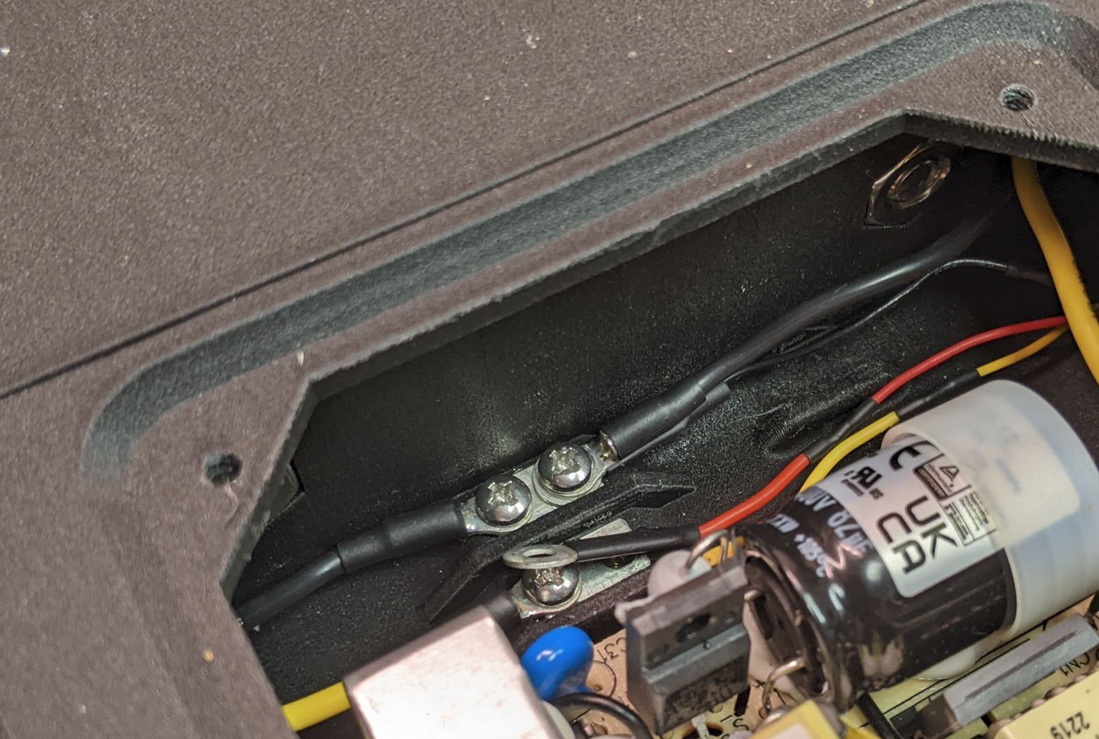
Place the two jumper plates onto the screw terminals on the power module case and then screw the ring terminals of the DC output cable onto the screw termianls with #4-40 PHMS, .25in Lg.
Note that it does not matter which ring terminal goes to which screw terminal, but make sure you match up the power and ground between the two sides of the screw terminal.
With the rubber fan cushion. If necessary, cut a small notch out of the fan cushion so that it can fit onto the fan frame without interfering with the wires.
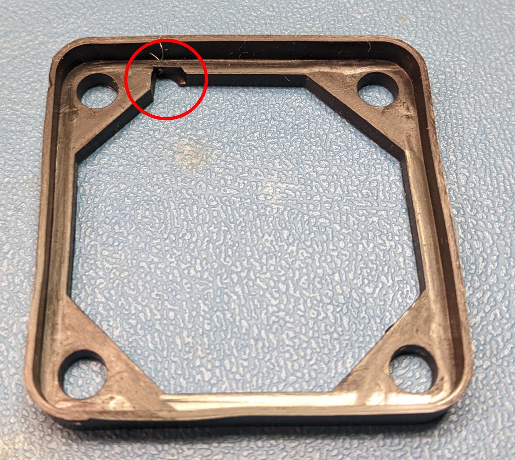
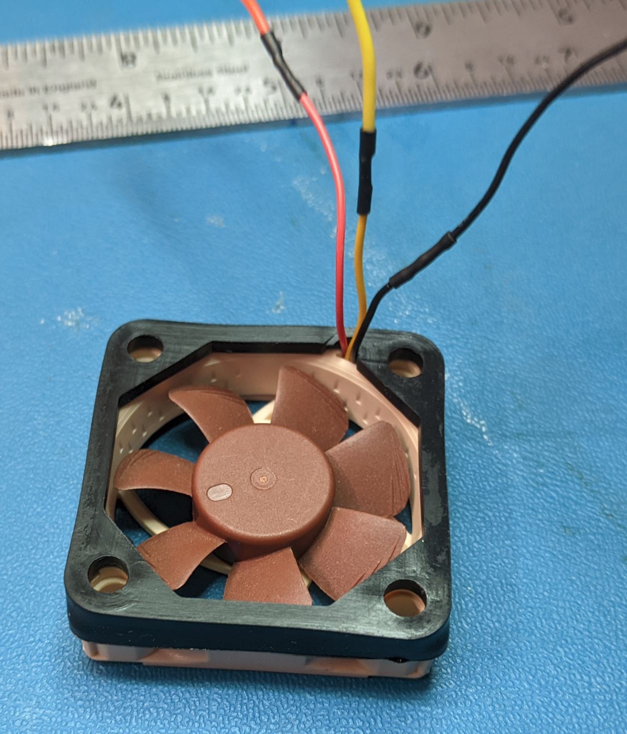
Fit the fan cushion over the inlet side of the fan (the fan will typically have arrows on the frame indicating the direction of airflow). The wires should come out of the inlet side of the fan as shown.
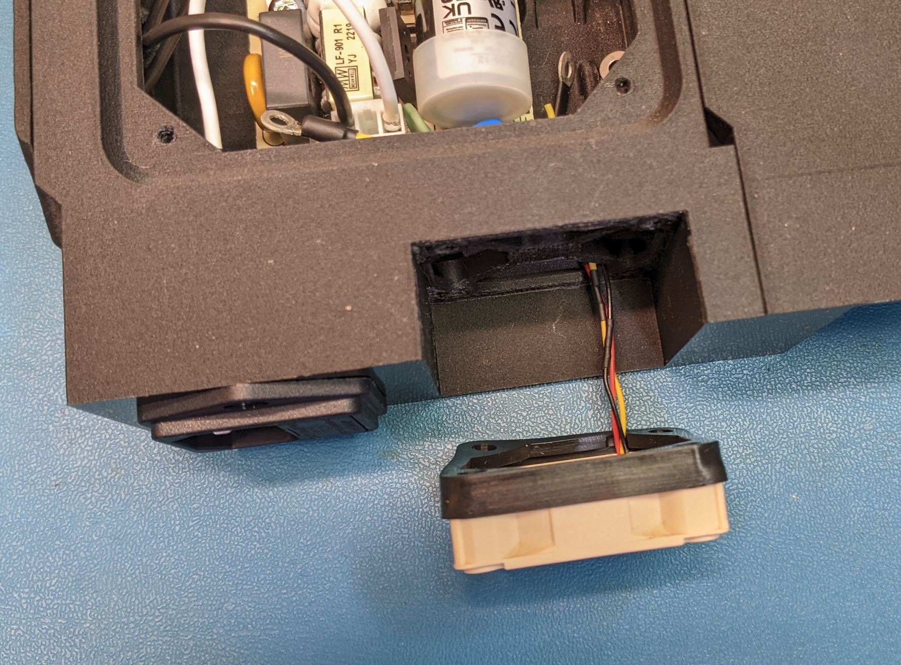
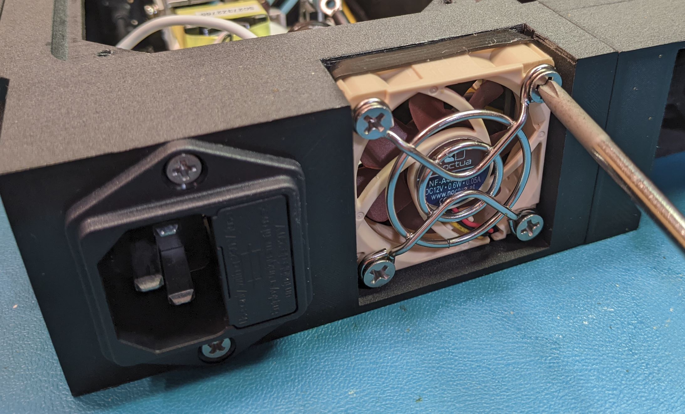
Slide the fan into place on the back of the power module case. The wires should be positioned to be at the bottom of the case. With the fan in place, put the fan guard on the outlet and attach it in place with four #6 self tapping flat head screws, .75" LG.
Note that the fan cushion will have a tendency to fall off the fan frame until you have everything tightened down. Make sure the fan cushion is still in place before installing the screws.
Connect the DC output wires and the fan wires to the other side of the screw terminals. Make sure to match up the power and ground wires correctly. Screw down the wires with the #4-40 PHMS, .25" LG.
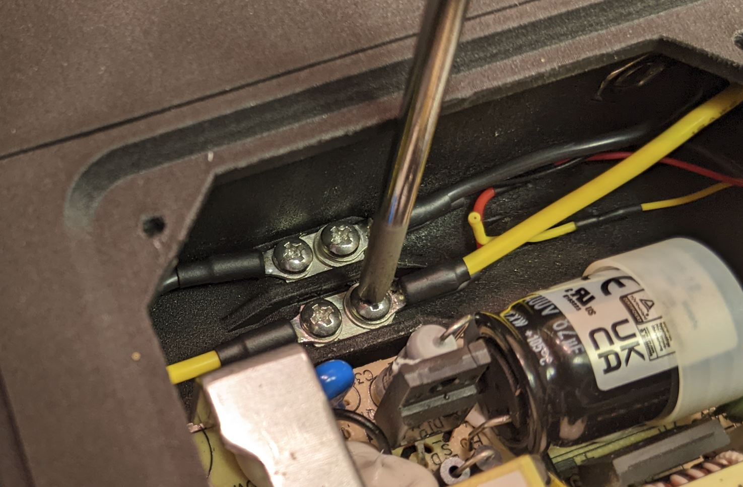
Note that the convention for fan wire color appears to be different. For the fans I used, the red wire is 12V and black is ground. The yellow wire is the RPM output signal, and is not used.
Match up the power and ground wires on the screw terminal and make sure everything is tight. I put the fan ring terminals underneath the output wire ring terminals, but either way will work as long as everything has good electrical contact.
Review the wiring setup and the pictures above. Make sure that the power and ground signals are routed as shown and that all of the wires go to the proper places on the switch and AC/DC converter. Also make sure that none of the wires are making contact with any part of the AC/DC converter. Before testing, switch the power switch into the 'off' position.
If everything is wired properly and all connections are plugged tight, it is time to power it up. Connect an AC cable to the power entry module in the back of the device. (Fueses??)
Nothing should happen at this point, as the power switch is off. Verify this by observing the LED on the output side of the AC/DC module, it should be off. If you want, you can check the DC output wires with a multimeter, they should not see any voltage. However, do not put test leads inside the power module case. instead, probe the other side of the DC output wires (where they go into the first device module). The fan should be off at this stage.
Switch on the power switch. At this point, the LED on the output side of the AC/DC module should light, and the fan should start to spin. Verify that 12V is present at the DC output wires in the expected polarity (black is ground, yellow is +12V).
If the device does not operate as expected, stop and figure out why before continuing.
Note: I generally wear safety glasses when applying first power to a high voltage circuit like this. This is a pretty simple circuit, so the likelihood of anything bad happening is pretty low. If you want, you can apply first power on a circuit that is protected with a GFCI device. This should interrupt power before anything too bad happens if you happen to inadvertently touch the device during operation. Don't take that as an excuse to be lax on safety.
If everything works as expected, switch the device off again and disconnect the AC power cable. Wait a few min before continuing to make sure the capacitors on the AC/DC converter are discharged.
Install zipties (.13" width or so) to hold the wires away from the AC/DC converter.
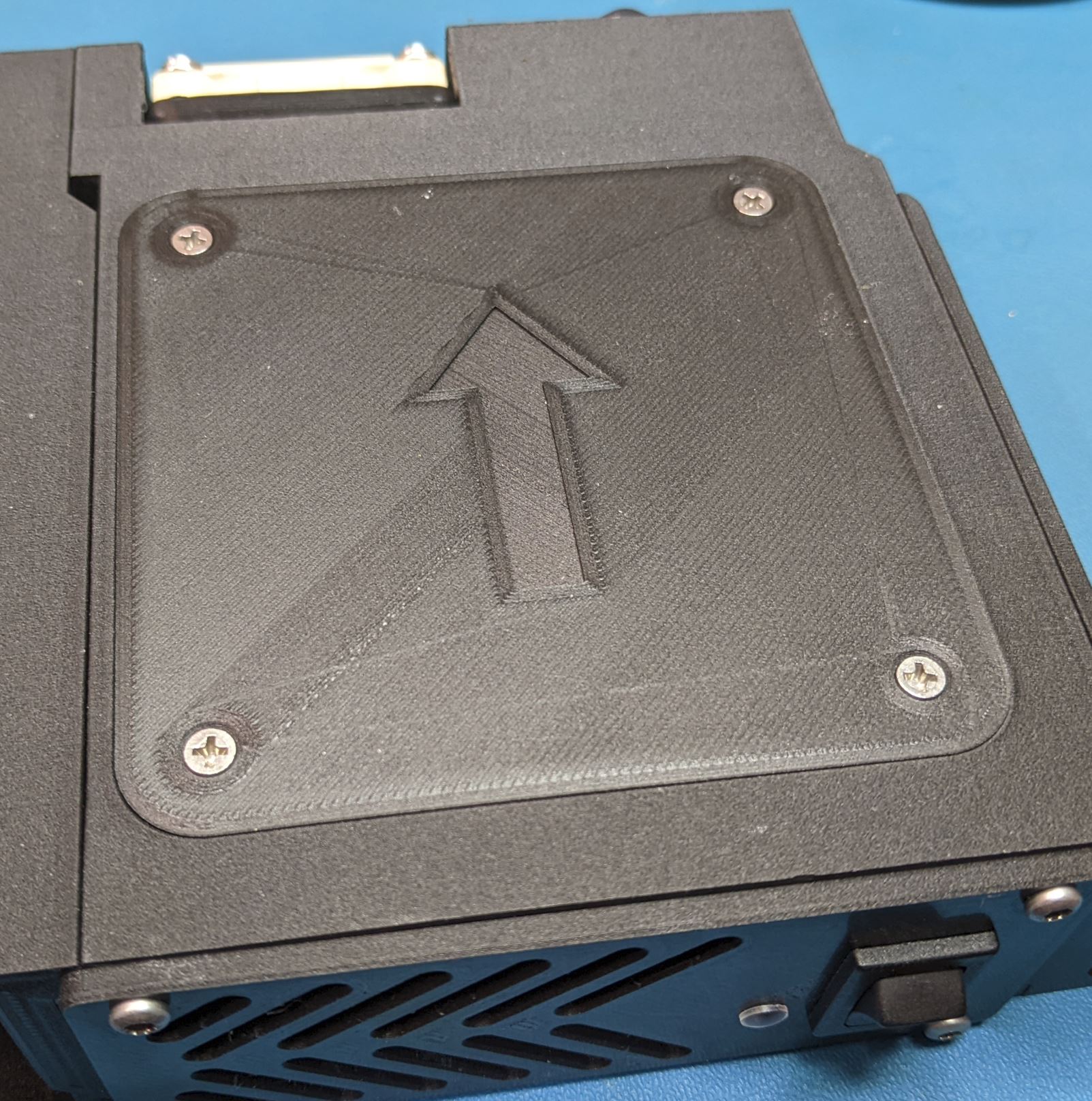
Place the cover on the power module case with the arrow pointing towards the back. Install the four screws (#4 self tapping, 3/8" lg) to secure the cover.
Perform step 7 again to verify that things still work. I recommend disconnecting AC power from the device for the rest of the assembly unless it is needed for testing.