THIS WATCH CONSISTS ENTIRELY OF BREAKOUT BOARDS AND IN-HOUSE FABRICATED PCBs. I was unable to make this version work on a PCB due to voltage regulator issues. So, I switched to the protoboard. If you plan on replicating this project, please do yourself a favor and add a functional buck converter. I created a significantly improved version here: https://github.com/choicebuilds/JWatch

The Bumwatch is truly made for bums - it has all the features a bum needs and nothing else. A very minimalistic display displays two things - steps taken and their heart rate that updates every second.
We live in a world full of distractions and bum-inducing items. Technology is specifically designed to make our lives easier, which is synonymous with making us more of a bum. Instead of bleeding-edge features, what a bum needs is an accountability partner that gives them only what they truly need.
The BumWatch provides the satisfaction of progress through step counting that updates live to provide instant gratification and feedback. Also, knowing the average resting heart rate is 60-100, this would motivate the bums to lower their heartrate through exercise because they become aware they are a bum. Finally, when the bum idles for too long, there is a vibration feedback that reminds them they are a bum. If you want to stop being a bum, there is no better method than to create this watch.
This iteration of the BumWatch is made entirely in-house and costed $0 (not including time and labor). The BumWatch consists entirely of breakout boards (that I borrowed) placed and stacked neatly and soldered to a custom-PCB that was created using in-house PCB fabrication machines (I could not complete this part, so I used protoboards). Although I would never recommend this method (due to problems I will address as we go on), it was fun planning and watching everything come to fruition.
Essentially, you can use any electrical CAD software (I used KiCAD) to create a schematic and layout. Then, you export the Front Side Copper (gbr), Back Side Copper (gbr), Edge Cuts (gbr), and Drill Files (drl). Why only these four? Well, the available PCB fabrication machines in-house (LPKF Protomat and Protolaser) from my local makerspace makes it extremely limited for a few reasons:
- You cannot create vias - this makes layout extremely difficult since you have to cram everything on one side. In other words, every trace has to be on the back side since through-hole soldering without vias makes it so that the front side is not electrically connected. This also makes the watch larger than necessary.
- You cannot create solder mask or silkscreen - not exactly an issue for fabrication, but a giant headache for soldering & assembly (more on the PCB assembly section).
Is it still doable? Absolutely. Does it look cooler? Absolutely (lie). Will I ever do it again? Absolutely NOT. The time and effort spent on laying it out and assembling it highly outweighs just ordering a PCB from say JLCPCB. I was unable to do this since I was not able to order them on time (due to US customs taking forever) and falling victim to sunk cost.


We'll get to why I had to make two iterations (yet still failed to make the final version) down the line.
1x Arduino Pro Mini (MUST BE 3.3V Version)
- Small lipo batteries usually say they supply 3.7V. However, it will drop down from 4.2V when fully charged to 3.0V when fully discharged until it eventually gives out. So, either the breakouts must be rated within the 3.0V-4.2V range or we must use a voltage regulator/buck converter. Nevertheless, it has to be a 3.3V rated version unless you use a step-up converter that can supply 5V. Update: the voltage regulator on this one also had a 1V-1.1V dropout, so I ended up using an Arduino Nano.
1x SSD1306 (4-pin display)
- This was the only display I could find that fit my desired form factor that I could find in-person. There were many more options online, but I settled on this one since this version of the watch is not exactly the final version I want to use (i.e. I did not care).
1x Sparkfun ICM-20948 Breakout (IMU)
- The disadvantage of this one over the BNO055 (this was so old and inaccurate it was unusable) is that there is no integrated sensor fusion, meaning it displays the raw IMU data. However, this sensor is much newer and much more accurate than all the alternatives I have considered. In essence, it is better in every way as long as I can write an accurate step counter algorithm.
1x Sparkfun MAX30101 + MAX32664 Breakout (Pulse Oximeter and HR Monitor)
- The cool thing about this breakout is that it has a MAX32664 attached to it. The sole purpose of that chip is to take the raw data from the MAX30101 and use its internal algorithm to display the heart rate without me having to write any algorithms - very convenient.
1x Sparkfun BPM085 Breakout (Pressure Sensor)
- This ended up not being used in the final design because it was the only sensor rated at 1.8V-3.6V and the voltage regulator was a piece of junk. Also, I forgot to route the voltage regulator to the on/off switch meaning this sensor would always be on with the voltage regulator - as mentioned in the PCB Fabrication section, I ran out of time so I could not fix this issue.
1x Adafruit DRV2605L Breakout
- Every sensor above gave me a headache at some point for one reason or another, but this one just worked. Maybe Adafruit is superior to Sparkfun? (this is a joke.. or is it)
1x Vibration Motor
- Okay I lied, this isn't a breakout. But like you need a vibration motor to use the vibration motor driver right? This one is brand agnostic - just find a small vibration motor that fits your watch.
1x Adafruit USB-C Microlipo Breakout (USB-C Charging)
- Essentially, you can use this to charge/discharge your battery. It's only supports charging though, you do not use this to update your Arduino firmware. And also, it just works (to be fair, all the Sparkfun sensors had more complex wiring diagrams)
1x 3.3V Voltage Regulator
- I got this from my local makerspace and it was really, REALLY bad. The voltage drop after connecting one sensor was so large my multimeter displayed <3V (???). Luckily, all the sensors here except the BMP085 were rated 3V-5.5V, so I did not need this voltage regulator (i.e. I could connect it directly to the battery since it will always stay within 3V-4.2V.. update: the pro mini also had a terrible voltage regulator that outputted something along 2.7V). Due to this garbage of a regulator, I had to redo my entire layout and print an entire new circuit boards just because this voltage regulator was so bad (rant over). Why not use a buck converter? Simplicity and form factor of course. Also, this only crossed my mind after I created a layout that fit the smartwatch form factor. And considering this was not even the final version, I just could not bother to waste any more time on this. Please use a buck converter.
1x 3.7V LiPo Battery
- Pretty self-explanatory here, just find one that's not a coincell battery and is small enough to fit inside your watch.
1x On/Off Switch
- This can be any switch. It essentially creates an open circuit between the battery and all the sensors in order to save power when not used.
1x FTDL Basic Breakout (USB to Serial Converter)
- THIS IS NOT APART OF THE WATCH. The Arduino pro mini does not have a convenient port to update the firmware. So, you actually need this breakout to be able to push your Arduino sketches into the Arduino pro mini.
This part was a massive headache. I've soldered on a PCB with no solder mask or silkscreen before, but this one just caused a lot more problems than I would have liked. This was exponentially harder than the one I made before due to a lot of issues:
- Not everything is connected in the layout - the first layout was perfect and everything would have worked out if the voltage regulator did not have problems. However, the second layout was made throughout an all-nighter the day before my local makerspace was going to close. I thought of a brilliant plan to bypass vias because things were not connecting properly on time. Instead of connecting everything on the back side, I decided to connect all my 3.7V on the front side and create a singular via with a very short wire and solder to connect the front and back side. This only works if there are vias for every 3.7V holes. Since the makerspace was closed, I could not make another PCB with a proper layout.

- Misplaced sensors and improper traces - I flipped the pressure sensor backwards (it was right the first time, I don't even know how this happened) and the 3.7V on the voltage regulator comes straight from the battery instead of the on/off switch. I decided to add an on/off switch last minute, and I probably should not have made major changes before the deadline.

- The pins are pre-soldered onto the breakout - this should not have been a problem if problems 1 and 2 did not exist. However, in order to connect the 3.7V on the front side and remove a few pins to make layout easier (and more compact), I had to unsolder the pins and resolder them back together to connect them properly. Lesson learned - always, always double check your design before fabrication and do not trust your brain during an all-nighter.

- The through-hole copper is fragile - since I was not sure I had access to flux after the makerspace closed, I sanded the final PCB very hard with sandpaper over running water to prevent oxidation. Bad idea. After soldering, the copper surrounding the all the through-holes would fall off with the sensors if I yanked too hard. Either that or it probably happened due to having to unsolder/resolder many things due to the issues mentioned above. So, I had to manually create traces whenever this happened.

- Continuity Issues - I learned from the previous PCB I fabricated to make huge clearances. However, I finished half of it and came back after a week to realize there were my GND was connected to my SCL pin for some reason (?). After using an exacto knife to scratch around every single contact point, it was not a problem; but, the lack of solder mask and silkscreen is truly a pain.

You can stack the breakout boards together to reduce space. Also, you can cut the wires after soldering them to make them take up less space.
This part is extremely simple - it was a matter of copying preexisting libraries from the breakout boards and piecing them together. Here are the libraries for reference:
Display: https://github.com/adafruit/Adafruit_SSD1306 IMU: https://github.com/sparkfun/SparkFun_ICM-20948_ArduinoLibrary HR Sensor: https://github.com/sparkfun/SparkFun_Bio_Sensor_Hub_Library Pressure Sensor: https://github.com/adafruit/Adafruit-BMP085-Library Vibration Motor: https://github.com/adafruit/Adafruit_DRV2605_Library
The only difficult part was processing the IMU data and creating a step counting algorithm. With the help of AI, I essentially combined the movement of all axes and if that was greater than a certain threshold, it was counted as a step. Then, I set a cooldown period based on the average human step pace in order to avoid double counting. This only works if the user is actively swinging their arms while walking - putting your hands in your pocket would lead to inaccurate results. Considering this is a first prototype, I was satisfied with this.
If I did not have to redesign everything due to my voltage regulator, this would have looked much better. However, due to the frustration of everything stated above, I just created a bare minimum chassis for a working demo. Even then, it turns out I printed the wrong size before the 3D printing station had to shut down due to it being the end of the semester. Oh well.

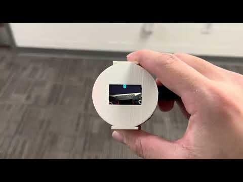
With all the power issues, I still wanted to make a final product. So, I decided to create a 4-layer protoboard watch in order to fit a watch form factor. After hours of soldering, I got tired of continuity testing. This ultimately meant I could not use half the sensors because there were continuity issues for my lower 2 layers. However, I was still able to create a working IMU and step counter. This product is no longer in development & I will be focusing all my efforts on the JWatch (link above). Here are some pictures for reference:


There are a lot of issues with this product. But all in all, with the fixes I mentioned above, I was able to create a functional product that works as intended, albeit not on the PCB. If anyone wants to expand upon this, please use a buck converter (step up if you wanna use 5V Arduinos, step down if you intend to use the pressure sensor or want consistent 3.3V output). Also, I would lay it out more compactly and properly with a professional PCB. Finally, the mechanical CAD is very bare-bones - there's much to improve in this aspect. I am satisfied with what I made since it was only a stepping stone to something bigger. I believe replicating this project as-is and making a working final product would be very helpful if you want to sharpen your debugging skills (please don't, you'll lose your hair over this).