- to render is to create an image
- interactive is to be able to affect whats shown in the screen
- chrome supports it
- linux has issues with hw support
- test support in (webgl)[https://get.webgl.org/]
- refresh rate, fps
- the eye, pinhole camera, view frustrum
- light: physical and virtual
- the graphics pipeline
- painter's algorithm | z-buffer
- physical 60fps, smooth 30fps, acceptable 6fps
- movies 24fps w/ motion blur
- tvs 60hz if 10fps => 6reps of image
- EU tv 50hz , 20ms p. frame
- 2.8 gHz = 2.810^9 * 0,02s = 5610^6 cycles p. frame
- if 100000 px per frame = 56 cycles p.pixel p.frame!
- GPU offer parallelism
- pinhole camera is like the eye, its like an image captured on film reversed as light passes thtough aperture
- eye sees correct side up but lense sees upside down
- frustum is a pyramid with the tip chopped off. it is the cone between the actual object and the image. with the tip of the cone between image and camera chopped.
- it is the sum of photons from the obejct reflected ion the image
- if we overlay a grid on a photo we see the concept of pixels of different color making the phto frame
- our screen is a window to a 3d world
- if i change my head position in the real world the window view does not change on screen
- our computer renders a 3d scene
- the scene is composed by 3d objects and a description that determines how light interacts with it. objects also can animate over time
- a camera is also defined in the scene that controls perspective
- the phtons from a light source reflect on surface pixels and enter into the camera aperture to form an image
- we need to compute only the photons that reach the camera
- we start from camera casting a ray. for simplification we caN assume there is no reflection but this is unrealistic
- non reflective materials (do not reflect other objects)
- graphics are rendered by a GPU with rasterization or scan conversion
- the steps are Application -> camera & model transform -> rasterization
- conversion of object surface in a collection of triangles
- application decides which triangles to set to the pipeline
- see if the object is in the view frustum. camera and model transform decides the tposition of each triangle on screen.
- the three points of the triangle are passed in aprocess of rasterization. if a point is off screen its clipped.rasterization fills the triangle with pixels
- each pipeline step is atomic and steps can run in parallel for multiple obejects harneshing GPU parallelism
- having 2 processors for a simple task cuts time in half if we split the action i half
- GPUs are design to optimize for multiple pipelines doing the exact same task
- the slowest atomic action determines the throughput
- slowest step causes starving to faster steps after it. as the others are waiting him to finish to get data
- it causes stalling to faster steps before it as they finished but cannot pass ahead their data as next step is busy
- in simplified pipeline a triangle goes down the pipeline to be put on image and be filled. what if we have 2 triangles overlaying.
- we use th e painteers algorithm where we draw the most distant object from the camera moving progressively toward the camera and drawing objects
- the flaw of this algorithm is that it can end up in vicious cycle where objects are overlapping eachoteher
- z is the distance from the camera
- in an image apart from storing the pixel color we store a z index 0.0 to 1.0 to specify its distance from the camera
- the default z -index for a pixelis 1.0 (far). if an object has z-index 0.6 and its triaangle wraps the pixel then the pixel gets ffilled with its color . if another object has z-index of 0.3 and contains the pixel the pixel takes its color. if another object has z-index 0.8 and conatins the pixel it is ignored fro the pixel coloring .
- if takes 1 cycle per action.(read z ind, write z-indez, add color) then we should draw objects from front to back
- webGL is an API based on OPenGL ES based on OpenGL
- webGl is raw with fine grain control over gpu but is code extensive.
- three.jl help us use less code
- option 1: change of camera/view angle
- option 2: two objects render coreclty based o view angle . one not its z-index is always lower (close to camera) overlaping others> fixed order
- option3: messed up draws front to back
- if our fps iof the screen is 60fps then he have 16.6ms to render each frame. if we take 12ms we dfont skip frames. if we do 21ms we show one every 2 frame so our frame rate is 30fps (frame skipping).
- if we need more thatn 1/30th of second we miss 2 frame updates of 60fps and we update every 3rd frame so fps drops to 20
- to average fps we convert to ms anfd then average it dividing with frames
- shadows cost a lot of computation
- if our camera is the source of ligfht. no shadows can be seen , objects are dimmer the further they are
- radiance gives perspective = lightfield(5 variables) 3 for location and 2 for direction. lightfield is the calculation of light coming fromany source antwgere
- npm init in project repo
- launch live-server
- open consdole
- fix typos
- see cube on screen
- RAPID PROTOTYPING
- sculpteo based in france prints 3d models
- intgerviewd in autodesk sf jesse harrington au
- 3d printing shortens product development lifecycle. model it -> 3d print it (at home or to a provider e.g shapewaves. review it. go to mass production
- use support material in gaps and wash it off after
- limits design contstrains
- helps make good design
- materials: bronze, metal all plastics
- printers take stl or obj files
- EXPENSIVE TO SCALE
- high res are slow
- in computer graphics we use points and vectors
- in 2d the point is defined by x,y
- in 3d graphics we use the cartesian coordinate system one point of reference (0,0,0) and 3 direction vectors x,y,z
- the points position is defined by (x,y,z)
- 3d vectors are described by a similar coordinate system. but the origin is not needed
- a vector represents a motion which is describved by 3 numbers. it describes how far to move to get from one point to another. the movement is not bound to any position in space
- distance or duration represents vector
- coordinate systems have orientation
- we have left handed and right handed system. the default is right handed with z axis pointing upward (thumb point to x + direction, index to y axis + direction and middle finger to z axis + direction)
- in left handed system the z axis + direction is downwards
- long/lat/alt is a right hand system as longitude increases left(east) and latitude increases north (up)
- minecraft as an example. in beta version x pointed south, z pointed west y pointed up (this is a assumption because the sun rised in the east)
- in final release x axis now points east z points south , y points up (sun rizes in south)
- both are right handed systems
-
there is no definite answer.
-
in tterms of actual world engineering xy is the surface and z is up. so in terms of screen it would be x left to right, z bottom to top and y towards the inside of the screen.
-
web developers use the following ccordinates. x left to right, y bottom to top, z towards the viewer
-
these 2 systems differ by a rotation of 90deg along to the x axis
-
experts say negative y up (towards viewer) so like the engineering approach or z up
-
coordinates transformation is tricky we need the drawing
- 3 basic primitives in graphics processing: points , lines, triangles.
- triangles the most important. everything you see in a computer game is a triangle
- we touch points and lines briefly to focus on triangles
- a point is defines by (x,y,z) and a line by 2 points of 3 coordinates each.
- a triangle is defined by 3 points of x,y,z coordinates
- point has 0 dimensions, line has 1 dimension , triangle has 2 dimensions
- in 3d graphics light reflection matters so surface, not whats inside the surface, the volume.
- in three.js we create a geometry object and add vertices to it.
// define geometry
var triangleGeometry. new THREE.Geometry();
// vertices
triangleGeometry.vertices.push(new THREE.Vector3(1,1,0));
triangleGeometry.vertices.push(new THREE.Vector3(3,1,0));
triangleGeometry.vertices.push(new THREE.Vector3(3,3,0));
// add a face
triangleGeometry.faces.push(new THREE.Face3(0,1,2)); // add vertices to face based on their index on vertix array
- the code above defines a triangle as an array of 3 vertex points with 3 dimensions and adds a face to it (surface)
- it is a questiion why a point is defined as a Vector3 object
- to show an objedct on screen we need geometry and material, then put them on a mesh and add it to screen. so to show the former triamngle geometry on screen we need to add
// set the material
var triangleMaterial = new THREE.MeshBasicMaterial({
	color: 0x2685AA,
	side: THREE.DoubleSide
	});
// combine geometry and material to a mesh
var triangleMesh = new THREE.Mesh(triangleGeometry, triangleMaterial);
// add mesh to the scene
scene.add(TriangleMesh);
- in this excersize we implement a function to set the geometry for a square
function drawSquare(x1, y1, x2, y2) {

	var square = new THREE.Geometry();
	// Your code goes here
	square.vertices.push( new THREE.Vector3(x1,y1,0));
	square.vertices.push( new THREE.Vector3(x2,y1,0));
	square.vertices.push( new THREE.Vector3(x2,y2,0));
	square.vertices.push( new THREE.Vector3(x1,y2,0));
	square.faces.push(new THREE.Face3(0,1,2));
	square.faces.push(new THREE.Face3(0,3,2));
	// don't forget to return the geometry!	The following line is required!
	return square;
}
- three.js library supports a 4 point face for squares
square.faces.push(new THREE.Face4(0,1,2,3));
- tessellate: from greek word for mosaic. is breaking an object in polygons of any sort
- triangulation: is to breake an object in triangles. usually we use the same vertices despite if we do triangulation or tesselation
- triangulation is a subset of tesselation
- gpus are optimized for triangulation and triangles as a triangle is always in the same plane
- a hexagon is minimum represented by 4 triangles without adding vertices
- a rule is that for a polygon of n edges we need n-2 triangles to represent it.
- high concavities reduce or eliminate the triangulation options for a polygon (without adding vertices)
- 3-D Computer Graphics uses an interesting concept to speed up object display. Backface Culling
- if we look towards a box only the sides of the box that facve towards us need to be rendered as they are visible. the backfaces of the box dont need rendering as they are not visible. Backface culling can throw away about half the face of the object so it speeds up rendering
- how the GPU decides whats backface and whgats frontface. in WebGl this is determined by the order of the triangle points. if the order is clockwise it is backfacing. if it is counterclockwise it is frontfacing. this rule is called right hand rule (right thumb up)
-
in three.js backface dulling is enabled by the MeshBasicMaterial config object property side: setiing its value to THREE.FronSide
-
in this exercise backface culling hides one of the 2 triangles so we dont see the square. we fix that by correcting the vertex order (right hand rule)
-
the fix is changing the order
geometry.faces.push( new THREE.Face3( 2, 0, 3 ) );togeometry.faces.push( new THREE.Face3( 2, 3, 0 ) );using the right hand rule
- manual creating triangles is a pain. a common way to create geometric objects is with 3d modelling software (like 3D studio max)
- models can be acquired by laser scanners
- these programs output a mesh of triangles.
- in WebGL and three.js there is a process where we can take a mesh in a 3D file format and convert it to a form that WebGL can read.
- write a regular polygon creator, a regular polygon around the axis origin.
- we have a function that generates the vertices based on the angle around the center
- draw a polygon wiki canvas
- our code
		// YOUR CODE HERE
		//Save the vertex location - fill in the code
		geo.vertices[pt] = new THREE.Vector3(x,y,0.0);
	}
	// YOUR CODE HERE
	// Write the code to generate minimum number of faces for the polygon.
	for (var face = 0; face<sides-2;face++ ) {
		geo.faces.push(new THREE.Face3(0,face+1,face+2));
	}
- our code is parametrical and takes polygon sides count as a pram.
- location will be the center of the polygon and passed as a THREE.Vector3(x,y,z).
- we can access its values to be used in the calculations as location.x location.y ...
- its easy . we add location.x and y to our polygon vertices coordinates
geo.vertices.push( new THREE.Vector3( x+location.x, y+location.y, 0.0 ) );

// or


		var x = Math.cos( angle ) + location.x;
		var y = Math.sin( angle ) + location.y;
- we pass a3rd parameter to our Polygon Geometry function . radius. as the ya re 1 by default
		var x = Math.cos(angle)*radius + location.x;
		var y = Math.sin(angle)*radius + location.y;
-
we will use the THREE.CubeGeometry() method to create 2 pieces per step . the vertical and the horizontal..
-
the params passed are (width, height, depth) or x,y,z
var stepVertical = new THREE.CubeGeometry(stepWidth, verticalStepHeight, stepThickness);
var stepHorizontal = new THREE.CubeGeometry(stepWidth, stepThickness, horizontalStepDepth);
- it generates triangles for us
- once w have this object we can use it multiple times to create 3JS meshes.. each of which consists of geometry and material
var stepMesh

// make and position the vertical part of the step
stepMesh = new THREE.mesh(stepVertical, stepMaterialVerical);
// the position is where the center of the block will be
// we can define possition as THREE.Vector3(x,y,z) or
const {x,y,z} = stepMesh.position; x = 0; y=verticalStepHeight/2; z = 0; //ES6 obejct destructuring, x=centereda t origin, y half of height: above ground plane, zcentered at origin
scene.add(stepMesh);
// make and position the horizontal part of the step
stepMesh = new THREE.mesh(stepHorizontal, stepMaterialHorizontal);
// the position is where the center of the block will be
// we can define possition as THREE.Vector3(x,y,z) or
const {x,y,z} = stepMesh.position; x = 0; y=verticalStepHeight + stepThickness/2; z = horizontalStepDepth - stepThickness/2; //ES6 obejct destructuring,
scene.add(stepMesh);
- we use plane grids to help us understand geometry. the lines are every 100 units
- the solution is
	for(var i=0 ; i<6 ; i++) {
		// Make and position the vertical part of the step
		stepMesh = new THREE.Mesh( stepVertical, stepMaterialVertical );
		// The position is where the center of the block will be put.
		// You can define position as THREE.Vector3(x, y, z) or in the following way:
		stepMesh.position.x = 0;			// centered at origin
		stepMesh.position.y = verticalStepHeight/2 + (verticalStepHeight + stepThickness)*i;	// half of height: put it above ground plane
		stepMesh.position.z = (horizontalStepDepth - stepThickness)*i;// centered at origin
		scene.add( stepMesh );

		// Make and position the horizontal part
		stepMesh = new THREE.Mesh( stepHorizontal, stepMaterialHorizontal );
		stepMesh.position.x = 0;
		// Push up by half of horizontal step's height, plus vertical step's height
		stepMesh.position.y = (stepThickness/2 + verticalStepHeight) + (verticalStepHeight + stepThickness)*i;
		// Push step forward by half the depth, minus half the vertical step's thickness
		stepMesh.position.z = (horizontalStepDepth/2 - stepHalfThickness) + (horizontalStepDepth - stepThickness)*i;
		scene.add( stepMesh );
	}
- we will add a birds hat, head, neck and body.
- we have a 2d blueprnt
- axis are x=red, y=green, z=blue
- we will use 3 3d shapes.
boxGeometry = new THREE.CubeGeometry(125.6 /* width */, 389.8 /* height */, 202.1 /* depth */);sphereGeometry = new THREE.SphereGeometry(202.1 /* radius */, 32 /* segs width , tesselation across the equator */, 16 /* segs height, tesselation pole to pole );cylinderGeometry = new THREE.CylinderGeometry(29.4 /* radius top */, 202.1 /* radius bottom */, 553.5 /* height */, 32 /* radius segments, amount of tesselation across the equator*/)
- we will add code in 3 functions
- createSupport() - base,legs, feet
- createBody() - body and spine
- createHead() - head and hat
- we follow the 2d blueprint to position shapes on axis. e.g body
// Body of the bird - body and the connector of body and head
function createBody() {
	var sphereMaterial = new THREE.MeshLambertMaterial( { color: 0xA00000 } );
	var cylinderMaterial = new THREE.MeshLambertMaterial( { color: 0x0000D0 } );
	// body
	var sphere = new THREE.Mesh(
	new THREE.SphereGeometry(58 ,32,16 ),sphereMaterial);
	sphere.position.x = 0;
	sphere.position.y = 160;
	sphere.position.z = 0;
	scene.add( sphere );
	// spine
	var cylinder = new THREE.Mesh(
	new THREE.CylinderGeometry(12,12,390,32 ),cylinderMaterial);
	cylinder.position.x = 0;
	cylinder.position.y = 355;
	cylinder.position.z = 0;
	scene.add( cylinder );
}
- z-fighting is when 3 shapes of different material ocupy exact same surface and try to overwrite the other causing wrong visuals
- we will work with colors and materials.
- app uses GPU to compute a color for each pixel and show it on screen
- the rendering pipeline is this:
- app sends a triangel to GPU
- GPU determines where the triangles vertices are on ther screen (including z-depth)
- each pixel inside the triangle is shaded
- if the pixel passes the z-buffer test it is saven on the image and displayed in the end of the frame
- In modern GPUs part of the pipeline is programmable
- the transfomed screen part done by the Vertex Shader: Vertex shader processes each vertex of the triangle. it uses info provided to it to manipulate each vertex in someway. e.g triangle color or vertices position. a standart operation of vertex shader is to output the location of the vertex on the screen.
- the triangle setup(non programmable): triamgle setup uses 3 screen locations generated by the vertex shader for an incoming triangle. Each pixel covered by a part of the triangle has a Fragment generated for it. this is Scan Conversion. Generated Fragments are sent to the Fragment Shader. (in directX this is Pixel Shader).
- Fragment Shader: Fragment Shader is provided info about the triangle being processed. like in vertex shader the programmer can feed any other data he desires. Fragment Shader outputs color and z-depth value. this value is tested against the z-buffer. if surface is visible the color is saved for that pixel
- This pipeline is called shader pipeline and used to compute color for each pixel the surface covers
- The pipeline goal is to EFFICIENTLY CALCULATE color and z-depth for a pixel.
- color is defined as an rgb value. each color of the 3 is called a channel
- if we swap channel we get odd looking color images
- colors are defined either as floats 0.0 to 1.0 or as integer: 0 to 255
- we will use floats (0.0, 0.0, 0.0) is Black and (1.0, 1.0, 1.0) is White
- in printing we use CMYK (Cyan,Magenda,Yellow,Black) which is like reversed RGB(CMYK subtrative color, RGB additive color)
- RGB is used in screens as we generate light with 1 being the maximum intensity. in Printing Colors absorb light.
- in 3JS we start by setting the material
var sphereMaterial = new THREE.MEshLambertMaterial();as we can set a color for the material - if we dont set a color for the material the default is white.
- the MeshLambertMaterial has several params. we can set them at constructor or later.
- one of the params is material color of type THREE.color
- we can set each channel separately
sphereMaterial.color.r = 1.0;
sphereMaterial.color.g = 0.0;
sphereMaterial.color.b = 0.0;
-
we can set all channels in once
sphereMaterial.color.setRGB(0.43, 0.32, 0,12); -
we can use hex to set a color
spherematerial.color.setHex(0x1220FF); -
we can pass the hexvalue color at material Constructor config object
var shereMaterial = new THREE.MeshLambertMaterial({color: 0xF343A3});
- rgb color space can be visualized as a cube where each color channel is an axis vector
- apart from the x,y,z we can add more params to the vertex like r,g,b color
- we can add colors when defining a face. e.g
geometry.faces[0].vertexColors = [color1,color2, color2, color3];where color is defined asvar color1 = new THREE.Color(0x423434);this adds a color to each vertex of the face - GPU interpolates the colors across the surface
- the function we iplenment is
function fillScene() {
	scene = new THREE.Scene();

	// Triangle Mesh
	var material, geometry, mesh;
	material = new THREE.MeshBasicMaterial( { vertexColors: THREE.VertexColors, side: THREE.DoubleSide } );
	geometry = new THREE.Geometry();

	// Student: add a colored triangle here
	geometry.vertices.push(new THREE.Vector3(100,0,0));
	geometry.vertices.push(new THREE.Vector3(0,100,0));
	geometry.vertices.push(new THREE.Vector3(0,0,100));
	var red = new THREE.Color(0xFF0000);
	var green = new THREE.Color(0x00FF00);
	var blue = new THREE.Color(0x0000FF);
	geometry.faces.push(new THREE.Face3(0,1,2));
	geometry.faces[0].vertexColors = [red, green, blue];
	mesh = new THREE.Mesh( geometry, material );

	scene.add( mesh );

}
- in the function we set the material to use vertexColors.
- we set 3 vertexes for the geometry of the triangle
- we add them to the face
- we set the vertexColor property to the face passing the colors for the 3 vertices
- we pash geometry and material to a mesh and we render it.
- the vertex colors are diffused with material color. as material color is white we see no difference
- in the previous quiz is important ot understand how triangle rasterization part of the pipeline actually interpolates acreoss the triangle. what is put on the vertex fades off across the triangle. if we color one vertex and leave others 0 (black) the color interpolates and diffuces to black going towards the other 2 vertices. this is used in materials and lighting
- the color triangle in the previous quiz gives an idea of the colors that can be displayed on a monitor
- CIE XYZ colorspace, along the curved edge are the spectral colors. the values are the wavelengths of light that produce the spectral colors.
- in the gamut there are lines or bands called mach bands. they are of special importance in computer graphics.
- monitor cannot produce pure spectral colors. each device has a color gamma. a triangle inside the gamut filled with colors it can display.
- the vertices of the color gamma are the same we used in our quiz
- better screens have larger color gamma. and priters use expensive ink to expand thir color gamma.
- If we have a red ball. how we make GPU compute how the lights in the scene and the balls material interact to make the ball look real.
- when performing interactive rendering we have different components added together: emissive, ambientdiffuse and specular.
- Emissive: for coloring glowing objects (e.g lightbulb) has its own color and other light sources dont really affect it. it is a way to add a constant color regarless of lighting conditions.
- Ambient: A fudge factor.something added to objects to look better especially in non directly lit areas. an ambient color value added to the fragments final color value. ambient and emissive are separate with different controls. 3JS allows setting ambient light to affect all materials with an ambient term.
- Diffuse: a flat, matte finish. it is determined by each lights location
- Specular: shininess of an object. it is affected by viewers location
- our light simplified model excludes light bouncing around from surface to surface. so non directly lit areas are considered bllack. ambient light helps adding some light to there areas to look more natural
- To sum up. The surface Color is computed with emissive component + ambient component. both solid colors.
- For each light there is a diffuce component depending on lights direction and a specular component depending on lights direction and view direction
- Surface Color = Emissive + Ambinet + For Each Light: Diffuse(Light) + Specular(Light,View)
- Equation: C + E + A + Σ(D(L) + S(L,V))
- we keep light fixed and show the effect on a sphere. we assume light is very far so we care only about its direction and not its position. so we dont have to think about the light direction changing as the object changes position. light is on top of the sphere. light effect is at maximum on top of the sphere goes to 0 at the equator and stays that way as the bottom stays away from the light
- a diffused material is defined as one that scatters light in all directions above the plane according to the cosine law. the amount of light gathered drops off as the angle gets steeper. The amount of a light from a single point on a surface drops off with the cosine of the angle of the surface compaerd to the eye
- A balancing factor is that as the angle of the surface to the viewer icreases the area of the surface visible through the pixel proportionally increases. we see more of the surface even less light per unit area is reflected to the eye.
- combined results on the position of the viewer to not matter as only the angle of light matters. faster rendering
- to shade a diffuse surface, we need the cosine of the angle between the direction to the light and the surface's normal (normalized vector)
- a vector operation called .product (εσωτερικο γινομενο διανυσματων) can be used to compute the cosine.
- First we need to normalize the surface normal and the vector to the light. normalizing is rescaling a vetor to have a length of 1. a dot product of 2 normalized vector gives a result of -1 to 1 which is used to compute the effect of lighting.
- if ihave a THREE.Vector3(3,-4,0) it represents a vector between (0,0,0) and the point defined. the vector length is var length=sqrt((3)^2+(-4)^2+(0)^2), by dividing each dimension x,y,z by the length we get the normalized vector
- given two normalized vetors,the cosine of the angle between them is computed by the dot product.
- given two vectors A and B the do product equals = Ax * Bx+Ay * By+Az * Bz
- we visualize x-y coordinate system. cosine is the projection of a radius=1 circle around the 0,0 on the x axis. or of the (1,0) vector to all normalized vectors of length 1 (points on the circle)
- dot product is the projection of one normalized vector on the other.
- dot product is a cummulative operation AdotB = BdotA
- in this excercise we will set a diffuse material
- to object has asolid color unaffected by light. to give this object a diffused material we need to change the material from THREE.MeshBasicmaterial to THREE.MEshLambertmaterial
- The Lambert material has several color components. the equation it uses is C=AMBIENT+COLOR*Σ(NdotLi) , NdotLi is the dor product of normalized vector with lighting
- the flat color material is
material = new THREE.MeshBasicMaterial({} color: 0x00FF00, shading: THREE.FlatShading}); - we can set color later as
material.color.setRGB()orvar newRed = material.color.r * 0.7; - we set ambient color as
material.ambient.setRGB();in this excercise initialy it is white but we make it color dependetn and it will be color*0.4 - Since the course's release, three.js has revised their material definition. The material's ambient color is now the same as the diffuse color, with the THREE.AmbientLight being the main way to adjust its effect. This will not affect this exercise's solution, but of course will matter if you use the latest version of three.js.
- Solution
function createBall() {
	// Do not change the color itself, change the material and use the ambient and diffuse components.
	// var material = new THREE.MeshBasicMaterial( { color: 0x80FC66, shading: THREE.FlatShading } );
	var material = new THREE.MeshLambertMaterial({color: 0x80FC66, shading: THREE.FlatShading});
	material.ambient.setRGB(material.color.r * 0.4,material.color.g * 0.4,material.color.b * 0.4 );
	var sphere = new THREE.Mesh( new THREE.SphereGeometry( 400, 64, 32 ), material );
	return sphere;
}
- In the previous quiz we saw that when we did not define the shading: THREE.FlatShading the surface was smooth
- To have a tesselated surface made of triangles look smooth, we introduse the idea of shading normal (normalized perpendicular vector)
- For a tesselated sphere the geometric normal for the triangles is discrete. as each triangle has geometric normals that are all the same acros the surface. so the triangle is flat and we dont have a smooth surface
- instead of geomatric normal we can satore a shading normal at each vertex. these are computated. in a sphere the normal at each point is the vecort direction from the center
- shading normal is made up and parametrical
- we take out shading: THREE.FlatShading
- when we dont define shading THREE.SmoothShading is used by default
- it uses a smooth shading normal at each vertex to compute effect of light and interpolate result
- Fragment Color = Ka * Material "Ambient" + Kd * Material(NdotL) "Diffuse "
- Ka is the grayscale level of ambinet light , Kd modify diffuse contribution
- HSL is a different color model Hue, Saturation, Lightness. hue is the color , saturation is how much color is used, lightnes is the light scale factor
var color = new Color(); color.setHSL(0.122, 0.433, 0.554);
- one technique to save gpu processing is to bake the light effect onto surfaces
- if i can calculate the shade of the object and store this color instead of the normal color, i can save light calculations for each frame.
- we assume that light is very far way but can change direction (like the sun)
- veretex shader takes as input the position of the object , vertex location
- it also tkaes the normal and the lights to be applied on object.
- output is screen position and RGB color
- we can bake if the lights direction and object orientation do not change
- materials that are diffuse reflectors: wood,concrete, newspaper
- materials that are shiny or glossy are specular materials, polish metals, plastics, glass. they look different when we view them from different angles.
- we need to take into account the direction from the surface to the eye
- a way to simultate these material is blinn-phong reflection model: the full formula has a number of terms in it for self-shadowing and for a shininess factor called the fernel coeficient.
- A simplecommon form is the following: Specular = MAX(NdotH,O)^s, maximum of NdotH or NdotH whichever is larger raised to a power.
- N is the surface normal
- H is the half angle vector
- If we have a surface, a light source direction, and a viewr angle. half angle is the normalized vector of a mirror that would reflet the light source directly to the eye. H vector splits the angle between the light source and the eye in half . so the angle between the half angle vector and the view angle is the same as angle between the half angle vectort ant the light source
- if surface normal matches the half angle then the surface acts like a mirror and the dot product is 1. if N and H angle is 90o the dot product is 0
- S factor is the shininess or specular power and has a power from 1 to infinity. 100 and above lrooks the same.
- a fraction to a power is a smaller number . shineness effect increases the smaller the number.
- the half angle represents the distribution of microfacets on a surface
- microfacet is a way of thinking how a material reflects light. a rough surface with a lot of angles reflects light with lower intencity
- when we compute lighting and interpolate like a column. its called gouraud shading. our eye is very good distinguishing areas where shading changes. they look like lines the mach bands. to avoid this we need to calculate shading more often , by using more triangles (increase teesselation)
- increasing tesselation makes lighting look better
- even then increased shiness creates problems.
- the number of triangle is larger across the edges of the shape, so increasing them stresses the GPU.
- another approach is t oevaluate the reflection model of each pixel.
- instead of interpolating rgb values that result from computing the effects of lighting, we calculate anything we need in the reflection model. in this case all we have to interpolate is the shading normal
- on the GPU we input in the VErtex Shader the position normal and in the output we have the screen position and instead of an RGB computed from the reflection calculation, we put transformed normal. so vertex normals are interpolated per pixel
- this interpolated normal is input to the fragment shader which then evaluates the reflection model and computes the RGB value to be displayed
- the per pixel interpolated normals will not be normalized
- each normal should be normalized before using it in the lighting computation
- when we interpolate normals and calculate the reflection model at each pixel, this is called per pixel shading or phong shading
- PHONG inventer the phong reflection model which gives a spectral highlight or a shingin spot. and phong shading which we discussed here
- in GOuraud shading color is computed at vertex and interpolated between the two
- 100 triangle * 3 vertex/triangle = 300 vertices / 5 triangles share a verte = 60 evals in Gouraud Shading
- 100 triangle * 60 pixels = 6000 evals in phong so 100/1
- up to now we were focusing on opaque materials where light hits the surface and bounces off
- in trasparent materials, light refracts and changes direction when it hits a transparent surface, it makes an object in the material look bent.
- transparency also changes light distribution on a surface (lense effect) focusing the light in spots
- these bright spots are called caustics
- color and intensity of light can be filtered by a transparent object
- the more the light travels through the object the more light gets absorbed.
- light refraction is GPU expensive
- light absorbsion throughthe material is also costy
- we will focus on light absorbsion on thin surfaces like filters and only for objecs that are behind the filter
- https://github.com/arodic/jellyfish, https://akirodic.com/about
- one way to think of transparency is that we want to see a bit of both objects
- if we have two objects on screen, one object and a filter on top of it. one approach is to blent the two by adding one every other pixel by the filter and one every other pixel the object behind it. THis algorithm is called SCREEN-DOOR TRANSPARENCY and is a 50/50 mix.
- this is a simple way to show an object behind a transparent object.
- the object behind is the destination and the object infront the source
- over operator is simply using opacity to blend the colors like in CSS.
- the final color is as*Cs +(1-as)*Cd . where as is the source alpha or opacity. with 1 fully opaque and 0 fully transparent.
- this is a form of linear interpolation
- an other operation in wbGl is the add
- the over operator shows a transparent effect by blending 2 objects
- but how z-buffer works when we are using transparent objects.
- z-buffer stores the depth of the object that is closer to the eye
- if we draw the further object first transparency will work.
- if we draw close object first the back object gets ignored by the z-buffer so there is no transparency
- draw back to front. dr4aw opaque objects first transparent later
- however if we stack filters (transparent objects) one behind the other, if we violate the first rule the second will not solve the problem
- so our only way to solve it is back to front.
- Three.js apllyes transparency by:
- Render all opaque objects first, z-buffer on
- turn on blending
- render transparent objects sorted back to front
- we still have interpenetration of transparent objects (zbbuffer and center point)
var movingBoxmaterial = new THREE.MeshLambertMaterial({
	color: 0xE53319, opacity: 0.4, transparent: true
});
* the problem in interpenetration is as objects surfaces cross and the view angle intersects with the crossing surfaces in two lines. in one case the one surface is infront and on the othe the other. so the draw order will always be wrong for one pixel or the other depending on which object gets drawn first

* in our example red object is rendered after yellow, and the red object is closer to the eye
- rendering transparent objects is more complex than simply sorting objects and drawing them.
- so far we dont show backfaces of transparent objects. if we turn them on we have strange artifacts
- assume we see an object from the side with the pahses in that order, 1 back,2 top,3front,4 bottom. the object is inclined to front.
- Phase 1 draws first and 2 blends with it. phase 3 is drawn filling z-buffer and blends with phase 1. phase 4 is behind phase 3 so is invisible. only 1 has an effect on rendering.
- even with back face enabled and good sorting order, we have problem with different sized objects.
- assume a white plane and a red object resting on it. both transparent. middle of the ground plane is closer to the eye so white plane is drawn after. so to the eye it seems the white plane is above the red object.
- complex objects can have two or more surfaces overlapping a pixel. draw order determines whats drawn on the screen. we have to control the order of the riangles on a surface to make it look right. this is unrealistic
- A technique that works well for complex objects is depth peeling. the idea is to peel away each transparent layer untill all layers are processed by storing an addtional z-depth for each pixel/. e.g 1st layer are all surfaces closest to he camera, 2nd layer are 2nd closest surfaces, 3rd layer
- this algorithm requires many passes
- a demo on depth peeling article
- we use an a buffer for each pixel with all the transparent fragments indexed by their depth order. we then combine the fragments in right order. it is possible in new GPUs. mobile devices use Tile-Based architecture.
- another approach is Stochastic Transparency it is Screen-Door Transparency with randmness to get a better average
- A futere technique is ray tracing
- Shininess: Hat,Body = 100, Leg=4, foot=30, Specular Color 0.5,0.5,0.5
- use MeshPhongmaterial
	var hatMaterial = new THREE.MeshPhongMaterial( );
	hatMaterial.color.r = 24/255;
	hatMaterial.color.g = 38/255;
	hatMaterial.color.b = 77/255;
	hatMaterial.specular = new THREE.Color(0x7f7f7f);
	//hatMaterial.specular.setRGB(0.5,0.5,0.5);
	hatMaterial.shininess = 100;

	var bodyMaterial = new THREE.MeshPhongMaterial( );
	bodyMaterial.color.setRGB( 31/255, 86/255, 169/255 );
	bodyMaterial.specular = new THREE.Color(0x7f7f7f5);
	bodyMaterial.shininess = 100;

	var legMaterial = new THREE.MeshPhongMaterial( );
	legMaterial.color.setHex( 0xAdA79b );
	legMaterial.specular = new THREE.Color(0x7f7f7f);
	legMaterial.shininess = 4;

	var footMaterial = new THREE.MeshPhongMaterial( { color: 0x960f0b } );
	footMaterial.specular = new THREE.Color(0x7f7f7f);
	footMaterial.shininess = 30;
- legs and feet are beveled for shininess
- shininess look better on spherical objects
- we need to add transparency to the bird body
- teacher added an inside object to simulate the fluid
- glass should be, 30% opaque, black regular black, specular color white.
- we have a paper lantern shading. inside and outside surfaces have the same shading, as normals have the same direction for inside and outside. this is not normal.
- a solution is to render the model twice: one with backface cull and a second with frontface cull and flip the normal
- a glass cube on a table problem. even with good techioques like depth peeling. a blue transparent cube on a wooden opaque table gives artifacts.
- bottom of cube has z fighting with table surface
- transform is an operation that changes the position, orientation, size and shape of an object.
- transforms are key parts of computer graphics
- when we set position of an object we use a type of transformation called translation.
- transformation in computer graphics is applied linear algebra. it is concerned with vector spaces
- a point is a position and a vector describes a motion.
- we can combine points and vectors in various points by adding or subtracting their coordinates from one to the other.
- if we subtract the location of point A from point B, we get a vectotr describing how we get from point A to point B. B-A = (Bx-Ax,By-Ay,Bz-Az) = V, A + V = B
- we can add and subtract vectors as well. S+T = U (e.g S,T,U are the fases of a treiangle with the vector direction S and t cccw and U cw)
- vectors can be multiplied by a scalar (its length is multiplied by the scalar)
- multiply by a negative scalar reverses direction and multiplies its length.
- multiplying a point by an number is a way to make the object look bigger.
- points and vectors dont require numbers to be associated with them.
- if i say define a vector from a point in the universe to another it exists, but has no coordinates until I define a frame of reference.
- if in the previous example I say what are the vectors coordinated in reference to the earths latitude,longitude and altitude?. this will define a set off coordinates for the vector. these coordinates with change every second as the Earth rotates. ( if i say what are the coordinates in terms of suns location and earths path). again i will get coordinates that change but slower.
- always i need a point o f reference when i set coordinates.
- in computer graphics we use the term world space, this is a user defined frame of refrence and usually right handed, we can add units to it or have it unitless if they are not needed.
- we treat point as a vector in linear algebra.
- 3JS library has many vector operations available. normalize() makes the vector a normalized one (length=1)
- translation is a way to move sthing in anew position.
sphere = new.THREE.Mesh(
	new THREE.SphereGeometry(104/2, 32, 16), sphereMaterial);
sphere.position.x = 0;
sphere.position.y = 540;
sphere.position.z = 0;
scene.add(sphere);
- translation and other transforms are built into every object.
- we can transform manualy by setting the position coordinates to a new set of values
- 3JS has built in support for object roation.
cube = new THREE.Mesh(
	new THREE.CubeGeometry(64,64,64), cubeMaterial);
cube.rotation.x = 70 * Math.PI/180;
- in 3JS the rotation happens on the axis we apply it to , it is counterclowise and gets as parameter the degree in rads
- we need to rotate the clock indexes to point to 2 and 8 o clock
cube.rotation.y = 2* Math.PI / 3;
- We note that there a re 3 rotation angles on the 3JS object. we can rotate along the x, y or z axis
- when controling a plane x-rotation is known as PITCH (head up and down), y-rotation as YAW/HEAD (left right) and z-rotation as ROLL
- these angles are called EULER angles
- combining these 3 rotation we change the frame of rotation as the frame of rotation is the current orientation of the object like in a robot arm.
- euler angles are use in flight simes, robotics and mobile devices as they can describe the mobile device orientation
- they suffer from the gimbal effect. if i rotate say 90deg the x and y rotation have the same effect, we lose a degree of freedom
- to scale sthing is to make it larger or smaller.
- rotation and translation are rigid body transformation as do not change objects body shape or volume.
- scaling
balloon.scale = new THREE.Vector3(3,3,3);*uniform scaling - scale is done in respect to an origin. as it it uses the Vector3
- we can do per axis scaling
cube.scale.x = 1;non-uniform scaling
- our aim is to sqeeze and elongate a sphere of radius 10 to look like a clock index (60 units long, 4 units wide and high). be careful that overall dimension is diameter so scale to 2r
	sphere.scale.x = 3;
	sphere.scale.y = 0.2;
	sphere.scale.z = 0.2;
	sphere.rotation.y = Math.PI/6
- up to this point we have been ignoring the order of operations.
- we didnt care what need to be done before the orther
- order matters whenb rotations and scales are involved.
- 3JS does it in the followin order: Scale->Rotate-> Translate.
- it doesnt matter what is the order in the code . the execution order is the one mandated by 3JS.
- if we rotated the clock index and then scaled, the rotation would have no effect. as rotating a spere nas no effect
- 3js interactive scene editor editor
- move the stick and place it as arms. center must be placed 50 units up
	cylinder.rotation.x = Math.PI/2
	cylinder.position.x = 0;
	cylinder.position.y = 50;
	cylinder.position.z = 0;
- in the previous example if we first translated to the new position and then rotated then the stick would be on the ground far from the snowman. this is because rotation is arount hte axis so a distance from the axis messes things up. when we rotate and translate the object is on the axis => gets rotated => moves to its final position
- we ve seen that 3JS doesnt let us easily position and rotate the hand of a clock. it rotates and positions when we want to do it in reverse order.
- a way to solve this is is to use Object3D to make a new object that contains our clock hand
var block = new THREE.MEsh(
	new THREE.CubeGeometry(100,4,4), clockhandMaterial
);

var clockHand = new THREE.Object3D();
clockHand.add(block);

clockHand.rrotation.y = -70 * Math.Pi/180;
scene.add(clockHand);
- the block is nested in the object3D clockHand object.
- the transition moves the block so that one end is over the centter of the clockface so that the hand will rotate around the clock properly
- no we have 6 available transformation 3 from block and 3 from Obkect3D wrapper. so we can overcome the order. <=TcRcScTbRbSbO we can pick whichoune to use following the order (b = block, c = object3d container) TRS is the order.
	cube = new THREE.Mesh(
		new THREE.CubeGeometry( 70, 4, 4 ), minuteHandMaterial );
	cube.position.y = 14;
	cube.position.x = 70/2 - 10;
	var clockHand1 = new THREE.Object3D();
	clockHand1.add(cube);
	clockHand1.rotation.y = -60 * Math.PI/180;
	scene.add( clockHand1 );

	var sphere = new THREE.Mesh(
	new THREE.SphereGeometry( 0.5, 32, 16 ), hourHandMaterial );
	sphere.scale.x = 50;
	sphere.scale.y = 4;
	sphere.scale.z = 4;
	sphere.position.y = 18;	// move the hand above the other hand
	sphere.position.x = 50/2 - 10;
	var clockHand2 = new THREE.Object3D();
	clockHand2.add(sphere);
	clockHand2.rotation.y = 30 * Math.PI/180;
	scene.add( clockHand2 );
- Parent -> CHild -> GFrandChild (Tree)
- we ve used object3D to give us access to more transformation combinations
- object3D was created for a more important reason. to create a parent-child relationship between 2 objects.
- when a child is connected to the parent. it is affected to what happens to the parent
- this is called sceen graph hierarchy
- we can make a car made of parts and move them all by translating the parent
- we think the transformations we want to apply and move step by step
- once we apply a transformation we forget about it
- draw a picture if it helps.
- undo the transformation if we are not moving to our goal.
-
Instanciationg is the idea that a single geometric set of triangles can be reused again and again. e.g for a lamp we might have different transforms for each bulb but htte bulbs all have the same mesh.
-
e.g reuse a cylinder
var lamp = new THREE.Object3d();
var cylinderGeometry = new THREE.CylinderGeometry(20,20,100,32);
for(var i = 0; i<10; i++) {
	var cylinder = new THREE.Mesh(cylinderGeometry, cylinderMaterial);
	cylinder.rotation.x = 20*i*Math.Pi/180;
	lamp.add(cylinder);
}
- lets see how hierarchy works in practice. we'll make a robot with two parts to its arm. forearm and upperarm.
- forearm is made of 6 pieces.
forearm = new THREE.Object3D();
var faLength = 80;
createRobotExtender(forearm,faLength, robotForeammaterial);
scene.add(forearm);
- createRobotExtender adds the geometry
- upper arm is created in the same way to rotate around the origin
- we are interestec on how these 2 parts hook together so that forearm is the child of forearm
forearm = new THREE.Object3D();
var faLength = 80;
createRobotExtender(forearm,faLength, robotForeammaterial);
arm = new THREE.Object3D();
var uaLength = 120;
createRobotCrane(arm,uaLength, robotUpperArmMaterial);
// move the forearm to the end of the ipperArm
forearm.position.y = uaLength;
// attach it to a parent/child hierarchy
arm.add(forearm);
scene.add(arm);
- when we rotate the arm, the forearm gets rotated
- forearm has its own transforms independent
- in this exercise we will add a body to the robot. this is done by the createRobotBody func
	// Move the forearm itself to the end of the upper arm.
	forearm.position.y = uaLength;
	arm.add( forearm );
	// scene.add( arm );
	// YOUR CODE HERE
	body = new THREE.Object3D();
	var bodyLength = 60;
	// Add robot body here, put arm at top.
	// Note that "body" is already declared at top of this code.
	// Here's the call to create the body itself:
	// createRobotBody( body, bodyLength, robotBodyMaterial );
	// ALSO CHECK OUT GUI CONTROLS FOR BODY
	// IN THE FUNCTIONS setupGUI() and render()
	// Note you'll have to add the body to the scene to get it to display.

	createRobotBody(body,bodyLength,robotBodyMaterial);
	arm.position.y = bodyLength;
	body.add( arm);
	scene.add(body);
- we finish the robot adding a hand (a second hand)
	handRight = new THREE.Object3D();
	createRobotGrabber( handRight, handLength, robotHandRightMaterial );
	handRight.position.y = faLength;
	forearm.add( handRight );

	handRight.rotation.z = effectController.hz * Math.PI/180;	// yaw
	handRight.position.z = - effectController.htz;	// translate
-
Normally matrix order matters. If I rotate, then translate an object, I'll get different result than if I transalte then rotate. However there are exceptions.
-
translation, scale and translate/rotate along the same axis
- reusable code
var color1 = new THREE.Color(0xF08000); //orange
var color2 = new THREE.Color(0x808000); //olive
var color3 = new THREE.Color(0x0982FF); //bright blue

geometry.fases[0].vertexColors = [color1, color2, color3];

sphere = new THREE.Mesh(
new THREE.SphereGeometry( 104/2, 32, 16), sphereMaterial);
sphere.position.x = 0;
sphere.position.y = 540;
sphere.position.z = 0;
scene.add(sphere);
- solution (we must put Mesh in the loop)
	for(var i=0; i<24; i++) {
		var cylinder = new THREE.Mesh( cylGeom, petalMaterial );
		cylinder.rotation.x = Math.PI/2;
		cylinder.position.z = petalLength/2;
		cylinder.position.y = flowerHeight;
		var petal = new THREE.Object3D();
		petal.add( cylinder );
		petal.rotation.y = 15*i*Math.PI/180;
		flower.add( petal );
	}
	for(var i=0; i<24; i++) {
		var cylinder = new THREE.Mesh( cylGeom, petalMaterial );
		cylinder.scale.x = 0.25;
		cylinder.position.y = petalLength/2;
		var petal = new THREE.Object3D();
		petal.add( cylinder );
		petal.rotation.y = 15*i*Math.PI/180;
		petal.rotation.z = 70*Math.PI/180;
		petal.position.y = flowerHeight;

		flower.add( petal );
	}
- we now have a good ovverview of the trasformation offered by 3js. 3js does not offer additional trasformations. we need to know their innerworks and code if we want to program and parametrize the vertex and pixel shaders in the pipeline
- using the chrome debugger isf we look into an Object3D object we will see a parameter called matrix.
- it is of typoe Matrix4 with a lot of numbers in it.
- this matrix holds the transform that changes the shapes shape,orientation and location. these changes are stoned in this array.
- we can multiply a coordinate represented by a pointer vector, by multiplying the mattrix. ang get a new coordinate.
- ANY OBJECT WE MAKE is represented by a bunch of points.
- these points are in the objects own sort of space
- if we make a cube with cube geometry it is centered around a point(position). we can transform the cube points by a transfer matrix to move, rotate and scale as we desire.
- a transform matrix is a 4x4 matrix. almost noone uses the Matrix3
- 4x4 matrix is preferred by the GPU.
- we can multiply a coordinate by a matrix: D = NC, D=[D1,D2,D3,D4], C=[C1,C2,C3,C4], N[4][4] = [N11,N21,N31,N41,N12...N44]
D1 = N11*C1 + N21*C2+N31*C3+N41*C4; D2 = N12*C1+N22*C2+N32*C3+N42*C4; ...
- points and vectors are mathematical entities representing locations and movements.
- when we give them coordinates we define where they are or where they move in comparison with a frame of reference.
- we use 3 coordinate values (x,y,z) for both point or vector.
- till now if a set of coordinates represeneted a vector or a point was conceptual
- when using matrices, the way we differentiate points from vectors is by putting a 1 (point) or 0 (vector) to the 4th coordinate
- this is an operation check when we use vector or point math.
- V+V=V (0+0=0), V-V=V (0-0=0),P+V=P (1+0=1), P-P=V (1-1=0), P=P=ILLEGAL, V-P=ILLEGAL,
- the usual default setting for aq matrix is what is called the identity matrix. it has 1s in the diagonal and zeros everywhere. it is represented by I and it has the following property D=IC D=C. if we multiply a coordinate by this matrix we get the same coordinate back.
- when we create a matrix in 3js by this call
var mtx = new THREE.Matrix4();is an identity matrix - if during our code run we wnat to reset the matrix to identoity we call
mtx.identity()
- if we want to change the location of a point, we use a translation matrix.
- this matrix has the translation movement put in the top three positions of the last column. the rest of the matrix is an identioty matrix. the multiplication that gives the new coordinates for the point are
Dx=Cx+Tx,Dy=Cy+Ty, Dz=Cz+Tz - if we multiply a vector by this matrix we get the same vector back. a vector has no location and cannot be translated
- the matrix notation we use is column-major form, there is also the row major form wehre points and vectors are rows and the translation matrix coordinates are storen in last row.
- directx uses row major form , webGL uses column major form.
- in memory matrices are stored in the same way (column after column for webgl, row after row in directx)
- applying multiple translation matrices. the tranlation coordinates are added.
- to set a Matrix4 at constructor , we can pass ther values as arguments (16values) row by row. it is easier to the eye to align them to look like a coulmn major form matrix, 3JS as we said stores them in memory in its own way (column by column) and we can confirm that with the debugger
- if we hust want to set a translation to the matrix we can use
mtx.makeTranslation(x,y,z); - to apply a Matrix4 to an Object3D set the matrix property of Object3D = to he matrix already set as Matrix4. we also need to set matrixAutoUpdate property to falso to disable the Object3D build in transform (Posisition,Rotation and Scale)
var mtx = new THREE.Matrix4(); //identity matrix
mtx.makeTranslation(x,y,z);
forearm.matrix = mtx;
forearm.matrixAutoUpdate = false;
- there are many ways to form rotation matrices.
- arotation around the Z-axis is done by adding to an identity matrix the cosθ and sinθ in the first column top positions and -sinθ and cosθ in the second column top poisitions. z coordinate is left untouched as we rotate around z. the rotation is ccw. we can understand it as rotating the point vecor by θ or by turning the frame of reference by θ and calculating the new x, y so that the point vector has length of 1
- the dot product of the point coordinates and the rotation axis gives the new location
- 1st ew rotate the point and see its new coordinates.2nd we rotate the axis and see the points coordinates to the new axis (dot product of point vector and axis vectror)
- the whole definition for the dot product is the following. AdotB = (cos of angle between A and B)x(Length of A)x(Length of B). this is the dot product for non-normalized vectors
- we can think of a coordinate as moving due to the rotation or staying still and being recalculated for a new set of axes. the 3 coordinate axes are called the basis
- there is a easy way to add axis/angle rotation to a Matrix4 using
mtx.makeRotationAxis(axis, theta) - our cube has faces of length=2 and is centred on the frame od reference. we want the cylinders on the diagonals of the cube. step 1, find out around which axis to rotate, step b define the angle,
- the answer is -x and z
- i have my angle of rotation, its -x,z
- i need the angle of rotation and the cylinders lengt
- the 3js code to calculate the length of the cylinder is
// get two diagonally-opposite corners of the cube
// and compute the cylinder axis direction and length
var maxCorner = new THREE.Vector3(1,1,1);
var minCorner = new THREE.Vector3(-1,-1,-1);

var cylAxis = new THREE.Vector3();
cylAxis.subVectors(maxCorner,minCorner);
var cylLength = cylAxis.length();
- we need the angle of rotation
//take dot product ofcylAxisand Up vector to get cosine of angle
cylAxis.normalize();
var theta = Math.acos(cylAxis.dot(new THREE.Vector3(0,1,0)));

//or

var theta = Math.acos(cylAxis.y);
- for a tilted cylinder we were able to look at and think about axis we had torotate to.
- usually this is not the case. if we have arbitrary vector and try to find quickly the axis of rotation it is imposible.
- There is a quick way to get the axis of rotation, its called the cross product. paper
- in 3js its called like this
var rotationAxis = new THREE.Vector3();
rotationAxis.crossVectors(cylAxis, new THREE.Vector3(0,1,0));
-
it takes 2 vectors as its inputs, and the result is put into a 3rd vector. this vector is in fact the axis of rotation or at least one of them. the direction is deetermined by the right hand rule. we wrap our hand arount the first vector (cylinder) to the second vector (the y axis). our 4fingers poin to the axis of rotation, if we swap the 2 vector we get the oposite rotation axis.
-
the length of the cross product is proportional to the sin of the angle between the 2 vectors.
-
if the length of the corss product is zero or close to zero. the 2 vectors point to the same direction or the opposite direction. we can use then the dot product to figure out which case is true.
-
in this case the rotation axis we get is 0,0,0 so no rotation axis at all. if they are oposite we choose arbitrarily one axis perpendicula to the vectors and use it for rotation.
// special case: if rotationAxis is just about zero, set to X axis
// so that the angle can be given as 0 or PI
if(rotationAxis.length == 0) {
		rotationAxis.set(1,0,0);
}
rotationAxis.normalize();
-
Math notation: LENGTH(A X B) =sinθ x LENGTH(A) x LENGTH(B)
-
A -> (Ax,Ay,Az)
-
B -> (Bx,By,Bz)
-
A X B = (AyBz -AyBZ, AzBx-AxBz, AxBy-AyBx)
-
in the end we have a vector that represents the axis of rotation to go from vector a to vector b
-
this vector is perpendicular to these 2. we need to normalize it.
var cylindren = new THREE.Mesh(
 new THREE.CylinderGeometry(0.2,0.2,cylLength,32),cylinderMaterial);

var rotationAxis = new THREE.Vector3(1,0,-1);
// makeRotationAxis wants its axis normalized
rotationAxis.normalize();
// dont use position, rotation, scale
cylinder.matrixAutoUpdate = false
cylinder.matrix.makeRotationAxis(rotationAxis, theta);
- We implement our solution
// get two diagonally-opposite corners of the cube and compute the
	// cylinder axis direction and length
	var maxCorner1 = new THREE.Vector3(  1, 1, 1 );
	var minCorner1 = new THREE.Vector3( -1,-1,-1 );
	var maxCorner2 = new THREE.Vector3(1,1,-1);
	var minCorner2 = new THREE.Vector3(-1,-1,1);
 	var maxCorner3 = new THREE.Vector3(1,-1,-1);
	var minCorner3 = new THREE.Vector3(-1,1,1);
	var maxCorner4 = new THREE.Vector3(-1,1,-1);
	var minCorner4 = new THREE.Vector3(1,-1,1);
	// note how you can chain one operation on to another:
	var cylAxis1 = new THREE.Vector3().subVectors( maxCorner1, minCorner1 );
	var cylAxis2 = new THREE.Vector3().subVectors( maxCorner2, minCorner2 );
	var cylAxis3 = new THREE.Vector3().subVectors( maxCorner3, minCorner3 );
	var cylAxis4 = new THREE.Vector3().subVectors( maxCorner4, minCorner4 );
	var cylLength = cylAxis1.length();

	// take dot product of cylAxis and up vector to get cosine of angle
	cylAxis1.normalize();
	cylAxis2.normalize();
	cylAxis3.normalize();
	cylAxis4.normalize();

	var originalAxis = new THREE.Vector3(0,1,0);
	var theta1 = Math.acos( cylAxis1.dot( originalAxis ) );
	var theta2 = Math.acos( cylAxis2.dot( originalAxis ) );
	var theta3 = Math.acos( cylAxis3.dot( originalAxis ) );
	var theta4 = Math.acos( cylAxis4.dot( originalAxis ) );
	// or just simply theta = Math.acos( cylAxis.y );

	// YOUR CODE HERE
	var cylinderGeometry = new THREE.CylinderGeometry( 0.2, 0.2, cylLength, 32 );
	var cylinder1 = new THREE.Mesh(cylinderGeometry, cylinderMaterial );
	var cylinder2 = new THREE.Mesh(cylinderGeometry, cylinderMaterial );
	var cylinder3 = new THREE.Mesh(cylinderGeometry, cylinderMaterial );
	var cylinder4 = new THREE.Mesh(cylinderGeometry, cylinderMaterial );
	//var rotationAxis = new THREE.Vector3(1,0,-1);
	var rotationAxis1 = new THREE.Vector3();
	rotationAxis1.crossVectors(originalAxis,cylAxis1);
	// makeRotationAxis wants its axis normalized
	rotationAxis1.normalize();
	var rotationAxis2 = new THREE.Vector3();
	rotationAxis2.crossVectors(originalAxis,cylAxis2);
	// makeRotationAxis wants its axis normalized
	rotationAxis2.normalize();
	var rotationAxis3 = new THREE.Vector3();
	rotationAxis3.crossVectors(originalAxis,cylAxis3);
	// makeRotationAxis wants its axis normalized
	rotationAxis3.normalize();
	var rotationAxis4 = new THREE.Vector3();
	rotationAxis4.crossVectors(originalAxis,cylAxis4);
	// makeRotationAxis wants its axis normalized
	rotationAxis4.normalize();
	// don't use position, rotation, scale
	cylinder1.matrixAutoUpdate = false;
	cylinder2.matrixAutoUpdate = false;
	cylinder3.matrixAutoUpdate = false;
	cylinder4.matrixAutoUpdate = false;
	cylinder1.matrix.makeRotationAxis( rotationAxis1, theta1 );
	cylinder2.matrix.makeRotationAxis( rotationAxis2, theta2 );
	cylinder3.matrix.makeRotationAxis( rotationAxis3, theta3 );
	cylinder4.matrix.makeRotationAxis( rotationAxis4, theta4 );
	scene.add( cylinder1 );
	scene.add( cylinder2 );
	scene.add( cylinder3 );
	scene.add( cylinder4 );
- teachers solution
var cylinderGeo = new THREE.CylinderGeometry( 0.2, 0.2, cylLength, 32 );
for (var i=0;i<4;i++) {
	var cylinder = new THREE.Mesh(cylinderGeo, cylinderMaterial );
	var x = (i<2) ? -1 : 1;
	var z = (i%2) ? -1 : 1;
	var rotationAxis = new THREE.Vector3(x,0,z);
	rotationAxis.normalize();
	cylinder.matrixAutoUpdate = false;
	cylinder.matrix.makeRotationAxis( rotationAxis4, theta );
	scene.add(cylinder);
}
- a reason that we use a 4by4 transformation is that the matrix can hold any number of t ransformations at once.
- e.g the Object3D rotation param. in the plane example we use th code
airplane.rotation.x = effectController.ex * Math.PI /180;
airplane.rotation.y = effectController.ey * Math.PI /180;
airplane.rotation.z = effectController.ez * Math.PI /180;
- the transformation order of this code is <= RxRyRZO
- internally a Matrix4 transform matrix is made for each rotation. then they are multiplied together.
- matrix multiplication is done as follows . e.g N=AxB where all are 4by4.
- element N24 is caluclated by multiplying the 4row of A with the 2nd column of B : N24 = A14xB21+A24xB22+A34xB23+A44xB24
- this multilplication is the dot product
- so the 3 rotations are 3 matrices multiplied together in 2 steps.
- we can multiply T or S matrices.
- the standar order of Object3D transformations is <= TRxRyRzO = M0 M is the Matrix of object. this practice of multiplying matrices is called concatenation
- We can chain together aor matricces that affect an object.
- Car(Mc=TRS) has Wheel(Mw=TRS) has Hubcap (Mh=TRS)
- The World matrix of Hubcap is W=McMwMh as is the product of the Matrices of its parents and itself. world matrix is called also model matrix
- R=RxRyRz (R is a rotation matrix itself).a product of rotation matrices is a rotation matrix.
- the product of series of translation matrices is translation matrix
- the product of series of scale matrices is scale matrix
Frames insight
- In previous lessons we have seen that the order of transforms for an object is usually rotate and then translate. also the notation is TR as the transformation are writen right left
- if we first translate then rotate we get a different scene. the notation is RT.
- another way of looking at it is that every transformation changes the frame of reference. e.g rotation rotates it and translation moves it.
- first transformation changes the frame of reference that transformations to the right of it will use. then the trasformation transforms the object in relation to this frame of reference, coordinates are always in reference to a point of reference.
- world space is the global point of reference but in out transformations we use model space and then transform it to world space.
- in a parent child relationship, child is oriented in respect to the parent and then transformed to world space
- if we put a transfromation after the orher we transform with respect of the view of the world of the previous transform,ation
- first matrix to the right of a given set of transformation matrices transfrorms the object with respect to the ranformations to the left (wtf ?!? it should be th eoposite). actually he derives this from MxMwMh so that h transforms in relation to the parents (on the left) fram of reference.
- You may want to try the Euler angle demo in Lesson 4 again to see how the X rotation controls the other two rotations, since it is applied last. By changing X, you change the frame of reference for how Y and Z rotation are applied.
- A scale matrix is an identity matrix with the 1s (except the last one) multiplied by the scale factor. the 11 element is Sx factor , the 22 element the Sy factor and the 33 element the Sz factor.
- scaling can mess up normals. we are no jst transforming points with Matrices, we are transforming shading normal as well
- running normals through a traslation matrix leaves them unaffected. they are vectors. also a rotation matrix do not affect them as they are rotated to the new frame of reference.
- if we uniformally scale an object with the matrix the normals are scaled to . we need to r enormalize them before using them
- if we non-uniformalyy scale objectts the normal vector gets stretched in one direction and is not perpendicular any nmore.
- to solve the problem we need to inverse and transpose a matrix.
- Matrix Transpose (M^T) with its columns and rows flipped along the diagonal. another way to define it is that its columns become the rows of the transposed matrix.
- the inverse of the matrix has the following property: (Matrix M)(Inverse of Matrix M) = Identity Matrix (MM-1) = I
- the inverse of a transform matrix undoes its effects
- inverse of a translate matrix with Tx,Tx,Tz is the same byt with -Tx,-Ty,-Tz undoing its effect.
- for rotation matrix the inverse is the transpose matrix.
- for scale matrix the inverse is multiplicative inverse.
- the inverse of a matrix represinting various transformations is not obvious.
- all graphics libs have matrix inverse:
Matrix4.getInverse(mtx)
- we have aproblem with transforming normal when using non-uniform scaling matrices. in that case we need to use the transpose of the inverse of the Transformation matrix (TI) or the invers of the transpse (IT)
- if thr transform matirx is transaltion we dont care as it does not affect vectors
- if it is a rotation matrix the transpose is inverse. so the transpose of the inverse so the inverse of the inverse so the same matrix.
- for scale if it is uniform we just normalize again the normal as it will be scaled.
- the traspose of the nverse is based on contravariant and covariant vectors.
- a transformation matrix worth mentioning is the mirroring matrix. it is an identity matrix where one of the diagonals is -1 and the rest 1. the object is mirrored allong the axis that is -1. another way is by
mtx.scale.z = -1; - a problem is that the order of faces is reversed so if we use backface culling we need to reverse it or we will have problem. if the order is ccw i nthe mirrored is cw
- so if we the original frame is right-handed the mirrored is left-handed.
- to see if an obect uses mirroring we use:
if(mtx.determinant()<0){console.log("mirror used");}
- what happens to normals if they transformed by the same mnirroring matrix used for transforming points? all the time
- the upper left 3by3 part of the 4by4 transformation matrix contains the linear transformation (rotations and scales). multiplication and addition is preserver in the linear part
- the upper right corner (3by1 column) holds the translations. translation values get affected by multiplications with other matrices. translations affect only points.
to extract T,R,S from a matrix in 3js we use
mtx.decompose(t,r,s)t and s are returned as vectors, r as a quaternion ( we will learn abou it in animation). quaternion is a compact way to store the angle and axis of rotation for a rotation matrix. quaternions can be easily interpolated between tehm. to interpolate between different rotations. - bottom row is always 0,0,0,1. the trasforms we lokked into in this chapter are affine transforms. parallel lines stay parallel when affine transformations are applied. in modeling we always use affine trasforms
- when we use perspective cameras we use the last row which we call projective transform
- webgl and 3js are in column order
- TRSO - we apply transform matrices right to left
- frame of reference is applied left to right
- (ΤR)S=T(RS) matrices are associative
- TR != RT marices are not (usually) commutative
- the transpose of a translation matrix is a projective matrix
-
3JS creates canonical objects. this is when you create an object around a point of origin and use transformations to move it into position.
-
for some kinds of modeling we need another apporach. id we want a chain of cones to build a tree. we need to define where the end of each cone will be located. this type of modeling when we ganerate an object with a program is called procedural moeling.
-
in the cullen routine the top and bottom variables are are Vector3 positions given the ends of the cone. we will have descriptions for other vars in the code. this function has a special case o the cross product.
-
we have to create the proper length cylinder and feed this method its axis direction and center.
-
my solution
// Dummy settings, replace with proper code:
	var length = new THREE.Vector3().subVectors(top,bottom).length();
	var cylAxis = new THREE.Vector3().subVectors(top,bottom).normalize();
	var center = new THREE.Vector3(bottom.x + (top.x-bottom.x)/2,bottom.y + (top.y-bottom.y)/2,bottom.z + (top.z-bottom.z)/2);
- teachers solution
// get cylinder height
var cylAxis = new THREE.Vector3();
cylAxis.subVectors(top,bottom)
var length = cylAxis.length();

// get cylinder center for transaltion
var center = new THREE.Vector3();
center.addVectors(top,bottom);
center.divideScalar(2.0);
-
once we sorted out how to place cones and cylinders, a handy method to write is one that creates capsules (cheese logs). capsule is a cylinder with a sphere covering eachend
-
we use instance. one geometry object for each end
-
Mycode
	// YOUR CODE HERE
	// Here's a sphere's geometry. Use it to cap the cylinder if
	// openTop and/or openBottom is false. Bonus points: use instancing!
	var sphGeom = new THREE.SphereGeometry( radius, segmentsWidth, segmentsWidth/2 );
	for(var i=0;i<2;i++) {
		var sphere = new THREE.Mesh(sphGeom, material);
		if(i%2) {
			if(!openTop) {
				sphere.position = top;
				scene.add(sphere);
			}
		} else {
			if(!openBottom) {
				sphere.position = bottom;
				scene.add(sphere);
			}
		}
- teachers solution
var capsule = new THREE.Object3D();
capsule.add( cyl );
if ( !openTop || !openBottom ) {
    // instance geometry
    var sphGeom = new THREE.SphereGeometry( radius, segmentsWidth, segmentsWidth/2 );
    if ( !openTop ) {
        var sphTop = new THREE.Mesh( sphGeom, material );
        sphTop.position.set( top.x, top.y, top.z );
        capsule.add( sphTop );
    }
    if ( !openBottom ) {
        var sphBottom = new THREE.Mesh( sphGeom, material );
        sphBottom.position.set( bottom.x, bottom.y, bottom.z );
        capsule.add( sphBottom );
    }
}
return capsule;
- once we have capsules in our arsenal we can make all sorts of stringy objects.
- we have helices of spheres. our goal is to make helices of capsules
- where two capsules touch we make one sphere not 2.
- also wemake sure that both ends of helix have spheres on them.
- we should not compute both points for each capsule in each loop iteration
- its more efficient if on each iteration we compute one of the points.
- we can increase radial segment to make them smoother
- my solution
	var top = new THREE.Vector3();
	var prevTop = new THREE.Vector3();
	var sine_sign = clockwise ? 1 : -1;
	var capsule

	///////////////
	// YOUR CODE HERE: remove spheres, use capsules instead, going from point to point.
	//
	var sphGeom = new THREE.SphereGeometry( tube, tubularSegments, tubularSegments/2 );
	for ( var i = 0; i <= arc*radialSegments ; i++ )
	{
		prevTop.copy(top);
		// going from X to Z axis
		top.set( radius * Math.cos( i * 2*Math.PI / radialSegments ),
		height * (i/(arc*radialSegments)) - height/2,
		sine_sign * radius * Math.sin( i * 2*Math.PI / radialSegments ) );
		if(i<=0) {w
			var sphere = new THREE.Mesh( sphGeom, material );
			sphere.position.copy( top );
			helix.add( sphere );
		} else {
			console.log(top,prevTop);
			capsule = new createCapsule(material, tube, top , prevTop , tubularSegments, false, true);
			helix.add(capsule);
		}
	}
- teacher solution
var helix = new THREE.Object3D();
var bottom = new THREE.Vector3();
var top = new THREE.Vector3();
var openBottom = false;
var openTop = false;
var sine_sign = clockwise ? 1 : -1;
bottom.set( radius, -height/2, 0 );
for ( var i = 1; i <= arc*radialSegments ; i++ )
{
    // going from X to Z axis
    top.set( radius * Math.cos( i * 2*Math.PI / radialSegments ),
        height * (i/(arc*radialSegments)) - height/2,
        sine_sign * radius * Math.sin( i * 2*Math.PI / radialSegments ) );
    var capsule = createCapsule( material, tube, top, bottom, tubularSegments, openTop, openBottom );
    helix.add( capsule );
    // after first capsule is laid down, don't need to draw sphere for bottom.
    openBottom = true;
    // make top of previous capsule the bottom of the next one
    bottom.copy( top );
}
return helix;
- note that we cannot just copy points with = as this copies memory position. we must use
newpoint.copy(oldPoint)
- add eyes , nose and crossbar to the bird
	// YOUR CODE HERE
	// Add a crossbar support, a nose, and eyes.
	// Crossbar: use crossbarMaterial and
	//   THREE.CylinderGeometry( XX, XX, XX, 32 ) for the tessellation.
	//   The cylinder should have a radius of 5, length 200 and be at height Y=360
	//   and rotated 90 degrees into position.
	cylinder = new THREE.Mesh(
		new THREE.CylinderGeometry(5,5,200,32), crossbarMaterial);
	cylinder.position.y = 360;
	cylinder.rotation.x = Math.PI/2;
	scene.add(cylinder);
	// Nose: use headMaterial and
	//   THREE.CylinderGeometry( XX, XX, XX, 32 ) for the tessellation.
	//   The cone should have a radius of 6 at the tip, 14 at the bottom, height 70
	//   It should be rotated 90 degrees and put into position at -70, 530.
	cylinder = new THREE.Mesh(
		new THREE.CylinderGeometry(6,14,70,32),headMaterial);
	cylinder.rotation.z = Math.PI/2;
	cylinder.position.x = -70;
	cylinder.position.y = 530;
	scene.add(cylinder);
	// Eyes: use eyeMaterial and
	//   THREE.SphereGeometry( XX, 32, 16 ) for the tessellation.
	//   Each sphere should have radius of 10 and be moved to X=-48, Y=560,
	//   then rotated 20 degrees left and right to make a pair.
	var spherGeom = new THREE.SphereGeometry( 10, 32, 16 );
	for(var i=0;i<2;i++)  {
		sphere = new THREE.Mesh(spherGeom,eyeMaterial);
		sphere.position.x=-48;
		sphere.position.y= 560;
		var eye = new THREE.Object3D()
		eye.add(sphere);
		(i%2)? eye.rotation.y = Math.PI/9:eye.rotation.y = -Math.PI/9;
		scene.add(eye);
	}
- remember that to twist the order of trasformation we must use OBject3D wrapper
- photons are emitted by light source, are reflected or absorbed on surfaces and are ariving to the eye.
- even mirror does not reflect 100% the photons. only 90,95%
- light is absorbed in its way by water drops, dust, particles in the air
- a simple light model ignores effects like polarization or fluorescence.
- we allow light filters to alter the color.
- light emitters can have any form as the effect of light is computed invertex or fragment shading.
- the simplest form of light is the directional light.
- this type of light is described only by the direction vector
- a real directional light is the sun. it is considered infinite far away and the direction to the sun is the same for every object on earth.
- in 3js the directional light is a light point we can move around. in reallity we change the direction vector not the location of the light.
- in some libraries we can set negative value to light intensity as it absorbs light from objects
- in 3JS we use light intesity between 0 and 1. over 1 is acceptable but beyond monitor abilities.
- a sample code to add a directional light
var light = new THREE.DirectionalLight(0xFFFAAD, 0.7); //set light color and intensity
light.position.set(200,500,600); // set light position in scene in realtion to frame of reference, actually the light direction vector from position to origin (0,0,0)
scene.add(light);
	var light = new THREE.DirectionalLight(0xFFFFFF, 1.5);
	light.position.set(-200, 200, -400);
	scene.add(light);
- for a point light we define a position in space and it emmits light in all directions. we set color and intensity like directional light
- its different from real world light as dsistance does not affect brightness. attenuation is not done for sake of vision. its easier to see a scene with point lights if there is no drop off with distance.
- we can use equations for how light is attenuated with distance.
- 3JS supports only one drop off mode, defien maximum distance. it turns light o zero
- ambient light in reality drops off at the square of the distance. we dont use that as in artificial scene light doesnt bounces off , only lights what it hits.
- in 3js scen we create artificial indirect illuminations with ambinet light
scene.add(new THREE.AmbientLight(0x222222);. this is a fudge factor - the ambient color is blended with the materials ambient color to give a solid fill color
var someMaterial = new THREE.MeshLambertMaterial();
someMaterial.color.setRGB(0.8,0.2,0.1);
someMaterial.ambient.copy(someMaterial.color);
- if dont add ambient color to matrial the default is white and scene ambient will add grey to the object.
- its better if material ambient color matches the diffure color.
- replace the ambient light in drinking bird scene with poiint light
var light = new THREE.PointLight(0xFFFFFF, 1.0);
light.position.set(1000,1000,1000);
scene.add(light);
- we want to place the pointlight at camera position (like miner's light)
- the function below is called every time a new image is to be rendered(e.g when we move the camera)
- both camera and light derive from Object3D. so we copy position before render.
headlight.position.copy(camera.position);
function render() {
	var delta = clock.getDelta();
	cameraControls.update(delta);
	renderer.render(scene,camera);
}
- in 3js a spotlight is similar to real world. you shine this type of light on sthing to make it the center of attention.
- it is like apoint light because it has a position.
- it is like directional like because it points somewhere.
- its difference is the cone of light it forms. the control parameter in3js is the angle where the cone ends (spotlight). also there is a fall off exponent like a specular light. as we increase it the light gets tighter
- id 3dstudio max spotlight it has a double cone with inner cone called hotspot.
- in 3js there only 1 ambient light but as many spotlights,pointlights and directional lights we want.
- replace drinking biird scene directional with a spotlight: (color: full white, intesity: 1.5, location: -400,1200,300 , angle: 20deg, expo: 1, target position: 0,200,0)
	var light = new THREE.SpotLight( 0xFFFFFF, 1.5);
	light.position.set( -400, 1200, 300 );
	light.angle = Math.PI/9;
	light.exponent = 1;
	light.target.position.set(0,200,0);
	scene.add( light );
- having more and more lights takes a toll the GPU. each light must be evaluated for surface shading.
- a solution to it is deferred rendering
- normally we render a surface, and the fragment color for each pixel is stored, if its the closest visible object. this is forward rendering.
- in deferreed rendering we store data of some sort in each pixel.
- there are variations with nameslike defered shading or defered lighting.
- a variation stores position,normal, material color and shininess at each pixel. we also draw in the z-buffer
- with defered buffering every point light has an upper limit of how far its light goes. this forms a sphere around the light
- each surface that is in the sphere is affected by the light. other shapes are used too,
- an objects shadow established its location in respect to surroundings
- rasterization focuses on triangles rendered from the eye. we have to eork to generate shadows
- a technique is shadow mapping. the scene gets rendered from the point of view of the light. what the light sees is lit. if the light doesnt see the surface it is in shadow.
- in 3js the only lights capable of casting shadows are spotlights and directiona lights. for directional lights we specify how the light extends.
- Shadow map algorithm creates a shadow image of a scene from the lights view called shadow buffer. the image is like a z-buffer
- to enable shadows in 3jS. we enable shadow map in render and tell spotlight to cas shadows. for each object we have choice to cast or not shadow. and receive or not shadows from other objects.
- this has to be done on each geometry/mesh not on the parent element (e.g Object3D)
- 3JS has traversal method to go through an object and its children and enable them in batch
renderer.shadowMapEnabled = true;
spotlight.castShadow = true;
cube.castShadow = true;
cube.receiveShadow = true;

bbird.traverse(function (object) {
	object.castShadow = true;
	object.receiveShadow = true;
});

// better traverese
bbird.traverse(function (object) {
	if(object instanceof THREE.Mesh) {
		object.castShadow = true;
		object.receiveShadow = true;
	}
});
- its a good practice for testing to render the light source.
- solution: add this line of code after creating the renderer in init(): renderer.shadowMapEnabled = true; In fillScene(), add this line after creating the spotlight: spotlight.castShadow = true; And add this line after creating solidGround: solidGround.receiveShadow = true;
- summary
- techniques
- with shadows we see patterns on the objects which are intense when the light is brighter.
- shadow mapping algo works by seeing the world by the lights point of view. the depth image form is then checked during normal rendering. the depth of the surface visible at a point is compared with the transformed depth of the shadow map buffer holds. this creates trouble.
- the pixels of the lights view don match entirely with the camera view.
- this creates surface acne (black patches on a surface)
- the ligh view says the surdface is 3.8m away of the light, the camera view says the surface is 3.81m away from light, as 3.81>3.8 the surface is considered in shadow
- a solution is shadow bias. this has a peter pan effect with the object detaching from its shadow.
- so far we have implemented local illumination models where the object is affected by light and the result is sent to the eye. light comes only from light sources, no loght is reflected from other objects.
- there are many more light tracks that can be tracked.
- a rendering technique that simulates this is called ray tracing.
- demo
- we saw how GPU sent each triangle to screen and rasterizes it.
- ray tracing fires rays from the eye through each pixel. objects are tested against each ray. the closest object found across the rays path is the one used to compute the ray color contribution.
- we can think of each ray from the eye as rendering one by one pixel.
- to find the closest object to this pixel is to send every triangle to the pipeline and try to rasterize it and use z-buffer fro finding closest object. this is SLOW.
- reaserch tried to optimize finding the closest object along the ray
- rasterization is fast because each triangle covers many pixels.
- in its simplest form ray tracing is similar to rasterization. ech ray finds the losest object along it. the effect of ligh on the surface s computed, result is displayed. for light to pass we assume that other objects dont block or reflect light
- to add shadows with ray tracing we shoot a ray from object to the light. if it finds an object blocking light is ignored.
- ray tracing enables to create true reflection in glass effects. for shining surfaces we spawn a ray in the direction of light reflection, what his ray hits is whats reflected in the surface. we spawn rays untill we hit a limit (WTF?!?)
- many algorithms, paul herbert, 256byte tube mr.doob interview
- ligt->object-diffuse object, light->mirror->object
- one way to track the various ways the light can take to reach the eye, is to shoot more rays per pixel, bounce them around in hope of finding light sources. this is called path tracing.
- it is noisy to begin with but gives good results given the time.
- demowiki
- this demo uses progressive rendering, shooting more and more rays and blending the result.
- photon mappingminecraft
- a pure path tracer is stragihtforward. we shoot more rays in sensible directions and sum up ther light contributions found. we shoot 10^5 rays per pixel or more. the more processing the better quality. photon maPPING and bidirectional traCINGtry to get the best of both worlds. the idea is to send rays from light emitters using rays depositing radiance where rays reach. scene is retraced from acamera point of view and light is gathered. path tracing can give uparallel realism given the the time. it is an actual light simulation,
- basic shadow techiques miss how lights trully cast shadows. all lights have an area. but shadow mapping assumes that light comes from a point far away. unless light is indeed a point (no bulb diffusion)
- the real shadow behind the object is umbra. it is when the light cone between object and light area is cut by surface, the area tha is not fully lit nor shadowed is penumbra.
- in a point of penumbra tge light that is visible correlates to how much light the location receives. so we set a vector of the point to one edge of area light and the other to the line defined by the point and object surface. this vector splits the light area in 2,. the area of light forming a cone to the point is the %
- developer of beast engine for games. (also in demo scene). illumination labs.
- soft shadows are closer to reality (umbra, penumbra). when light close to ocluder more hard shadows.
- if you look at the shadows in this scene we see they are completely black. this is wrong., in reality nothing is completely black. we add ambient light to compensate for that. with ambient light shadows still look flat. objects are not distinguishable.
- what we see is the light from light sources reflected into our eyes. but only a fraction of the light reflected on surfaces.
- this bounced indirect lighting is important to the scene. with it simulated the scene looks realistic. light bounce from surface to surface while reflecting. with each bounce the light gets weaker.
- a surface absorbs all but the component of light of its color which gets reflecgted.
- global illumination is when one object affects others appearancce.
- one light source in 3JS that attempts to simulate the surrounding bounced light in scene is the hemisphere light. it is considered as surrounding the scene lighting from every direction.
- it is like ambient light but: we assign a different color to the top and a different to the bottom.
- each objects normals determine the color light it receives from this source. any direction between top and vbottom gives a blend of the two colors. ( an elaborate type of it is diffuse map)
- a light we take for granted and not consider it as a source is the sky. in outdoor scen it gives the ambient light.
- in simulation shadows take a blue touch. without sun sky shadow is dark blue
- in most scenes treat sun and sky as two different cointributors. sky color sets mood.
- proper sky in interactive scenes is hard and performance expensivce
- a phenomenon between camera effect and light is fog. in real life fog is light absorbed and diffused by the atmosphere.
- inb 3JS we have 2 forms of fog. linear fog (min distance=fog starts, max distance = fog covers all). or exponential. we specify density particles. a demo called god rays (beams of light)
- godrays
- demo
- omni light in 3JS is a point light
- vary the light x and z direction by the cosine and sine of the angle
function render() {
	var delta = clock.getDelta();
	cameraControls.update(delta);
	light.position.set( Math.cos(effectController.angle*Math.PI/180), 1, Math.sin(effectController.angle*Math.PI/180));
	scene.add( light );
	renderer.render(scene, camera);
}
- note we need to add a parametrical code in render that gets called when we change parameters.
- the lights direction x^2+y^2+y^2=1 (cosθ)^2+(sinθ)^2=1
- in astronomy altitude is the vertical angle from the observerbetween horizon and star. azimuth is the horizontal angle on horizon from north to star
function render() {
	var delta = clock.getDelta();
	cameraControls.update(delta);
	// altitude
	light.position.y = Math.sin( effectController.altitude * Math.PI/180.0 );
	// azimuth
	var length = Math.sqrt(1 - light.position.y*light.position.y);
	light.position.x = length * Math.cos( effectController.azimuth * Math.PI/180.0 );
	light.position.z = length * Math.sin( effectController.azimuth * Math.PI/180.0 );
	scene.add( light );
	renderer.render(scene, camera);
}
- ambient: color
- directional: color,intensity,direction
- point (positional), color,intensity
- spot: color,intensity,direction
- in the spotlight exercise. the surface has shadow and sptlight umbra. this is a Phong material. if we change to lambert spotlight sdisapears, shadow remains. this is because spotlight is evaluated per vertex not pixel. lambert is evaluated per vertex. surface has 4 corners outside the spotlight so in lambert is skipped. we can fix that with many triangles in surface but thats process expensive
- there are different ways to view the world. fisheye lens, perspective view and orthographic projection
- like a 2d cad. a 3d projection in 2d. like cad views. its not like we usually percieve the world, it can create optical illusions.
- to define an orthographic camera in 3js we do two operations. 1) define a volume in space 2) move and orient that volume as we like.
viewSize = 900;
aspectRatio = canvasWidth/canvasHeight;
/// 1st step define the box volume(-x,x,y,-y,-z,z)
// Orthographic camera(left,right,top,bottom,near,far)
camera = new THREE.OrthographicCamera(
	-aspectRatio*viewSize/2, aspectRatio*viewSize/2, viewSize/2, -viewSize/2, -1000, 1000
);
-
the camera is thought to be on the +z end of the box and sized on x by y to form a viewport looking down the -x axis (on the example) and upting the +p direction
-
dont set canvas height and width as viewport size. set it on the scene world coordinates to avoid distortion
-
if we view our drining bird with the camera set with the above code we will see a sideview.
-
if we want a more interesting view (projection) we need to position and orient the camera differently. thi is done with the code below
// 2nd step
camera.position.set(-890,600,-480);
cameraControls = new THREE.OrbitAndPanControls(camera, renderer.domElement);
cameraControls.target.set(0,310,0);
- first line is a translation. moves the view box by an amount.
- the camera control code does 2 things. it sets what kind of mouse controller we want for the camera. a custom orbit and pan class extends the orbit controls class of 3JS.
- this control keeps camera oriented so that +y is always up.
- for more free but more difficult control the trackball control class could be used
- last line sets the target of the camera (where we look)
- in summary we set a view box a view direction and a viewer movement, z-buffer applies
- we look in depth at how this view box is defined and positioned. 1sat we define our camera object as looking at worlds -z and orientedso that the top of the camera faces the +y axis. the camera starts at the origin(0,0,0) like all objects.
- then we move the cametra to the position where we want to view our scene from(translate). we also tilt and orient the camera as desired(rotation). we ignore scale (zoom?!?).
- positioning the camera is simple. to compute the rotation needed to orient the camera, we use the lookat system. we define a target loCATION WHERE WE WANT THE CAMERA TO LOOK AT. this defines the -z axis of the cameras frame of reference (as if camera carries its coordinate system with it).
- the camera up vetor is Up:(0,1,0). we have look at we have Up so Xc is -Zc x Up (cross product).
- zc and xc are global vectors. Up is a camera frame of reference vector. Yc global vector is Xc x -Zc cross product (cross product uses right hand rule to give a vector that is perpendicular to both vectors)
- there is a 3JS lookat method on the camera itself. but usualy we use cameracontrols.target to move the camera around with the mouse. our position is (-2800,360,-1600)
cameraControls.target.set(-2800, 360, -1600);
- we ve seen how to position and orient a camera in world space. if we apply the C matrix to a camera w palce it in the world. but we want the oposite. to position the world in respect toi the camra. if we invert the C matrix we do exactly that. this is the View MaTRIX
- C: put camera in the world, V=C^-1 - View Matrix, VMObject M:modeling matrix, V:viewmatrix. put the object in cameras frame of reference.
- in ebgl or opengl these two matrices are put together as mocel-view matrix
- with the view transform ready we have all coordinates in the cameras frame of reference. what is left is define the view box space to contain everything we want to render. (set the stage)
- the orthigraphic camera's definition is to give a left,right,top, bottom,near,far set of values to define this box. these vals set the corners of the rectangular box in the view space of the camera.
- we first orient the world to the cameras view of things and then define the box with respect to the camera. usually left = -right, bottom = -top, near = 0.
- creeating the orthigraphic camera creates the projection matrix. P(VM)Object. the box defined by the projection matrix is in front of the camera, symmetric around view axis. this box is view volume and does a projection. we say take everything in the box and project it along the +z plane of the box to form an image. we look to the -z axis as our system is right handed coordinate system for the camera. y is up x is right (cartesian system)
- 3Js thinks of the orthographic camera as going in apositive direction, the far value is distance along the -z axis. our chain of matrix adds this projection to the front. the projection matrix is added next. when applied a coordinate will get a new value in the projections frame of reference.
- this frame uses Normalized Device Coordinates (NDC). these coordinates take values between -1 and 1 in x,y,z
- we have the 4by4 orthographic projection matrix [2/(R-L) , 0 , 0 , -(R+L)/(R-L), 0, 2/(T-B), 0, -(T+B)/(T-B), 0, 0, 2/(F-N), -(F+N)/(F-N), 0, 0, 0, 1]. It does scaling and translation
- perspective camera is like real life with objects in the distance being smaller. it uses the same sort of pipeline as before. internally we define a view matrix exacly like in orthigraphic. the difference lies in the projection matrix.
- in the perspecgtive view of the world objects get smaller as they go further away from the viewer. if something is farther away it needs to be larger in world space dimensions to appear the same size on screen.
- a simplistic approach are similar triangles with the tan being the same. a perspective view involves division
- when we multiply vector by matrix is dot product (multiplies and additions). this is where the forth coordinate for our points come into play. till now this forth coordinate was always 1 and the row empty
- we run a point through any set of modeling transforms aND the forth coordinate value of 1 is untouched. this changes with perspective projection
- demo
- perspective camera is set in 3JS similar to orthographic. the creation call has fewer params.
- near and far set the view frustum. distances of near and far palne are measured from the camera point. along a central axis. near AKA hither , far AKA yon
- fisrst arg of the perspective cam is the field of view. this is the angle between top and bottom planes of the view pyramid. in 3JS it is set in deg not rad.
- field of view with aspect ration defines the sides of the pyramid.
- in orthographic we defined the location of volume box sides. in perspecive vie cone we assume symetricity around the cnetral axis so we can define it with less arguments.
// PerspectiveCamera(fov, aspectRation, near,far)
camera = new THREE.PerspectiveCamera(30,aspectRatio, 1, 10000);
camera.position.set(-170,170,40);
cameraControls = new THREE.OrbitAndPanControls(camera, renderer.domElement);
cameraControls.target.set(0,50,0);
- if we want to change the camera parameters at runtime we need to call
camera.updateProjectionMatrix();
- use dat.gui library to add a gui element. name: field of view, range: 1 to 179 deg, start at 40deg
- we setup gui
function setupGui() {
	effectController = {
		fov: 40
	};
	var gui = new dat.GUI();
	gui.add( effectController, "fov", 1, 179 ).name("field of view");
}
- in render() we use updateProjectionMatrix to change fov
	camera.fov = effectController.fov;
	camera.updateProjectionMatrix();
- the perspective matrix formed from the 3JS params, is
[1/(aspect*tan(fov/2)), 0, 0, 0, 0, 1/(tan(fov/2)), 0, 0, 0, 0, (near+far)/(near-far), 2*near*far/(near-far), 0,0,-1,0] - the upper left 3by3 matrix are scale factors
- there is a translation factor for z
- the lower row has -1 in 3rd column and 0 in last.
- near anf far value sometimes are negative as we travel the -z axis
- we use +z for near and far as 3JS specifies thingds
- if near plane was behind the camera things would be wierd
- for fov: 90deg, aspect ratio: 1 (square), near 1 , far: 11. perspective amtrix =[1,0,0,0, 0,1,0,0, 0,0,-1.2, -2.2, 0,0,-1,0]
- the 4 coordinates produced if we multiply projection matrix with a point are x,y,z,w . they are called homogenous and are used for projection.
- what we do next with these values is divide them with w. this is called the perspective divide or the homogenous divide. what we keep from the divide are the first 3 coordinates x,y,z as the last will be 1 by default.
- we plot the original 3 points in the frustum and the projected 3 in the NDC viewport as yz plane. -z axis is right to the frustum and resulting axis is +z to the right in NDC
- devices of same size in different distance when are projected NDC the relative area of coverage in near plane stays the same.
- the front device was half the sizer the near plane and is half the ndc size further devices appear smaller. also middle device moves further to right.
- after projection and before division by W. we do clipping. say we have 2 points, we apply perspective transformation which gives homogenous coordinates. these two points form a line segment. say one point is inside the frustum and one outside the frustum.
- we are interested in the coordinates in the final view volume to project them in NDC sppace for rendering.
- clipping is done to line segments and triangle edges that poke out of frustum. an edge can be clipped by any number of faces of the frustum.
- for our example all points along the line are linear interpolated. the point of the funstrum faces halfway between two points. we divide this point with w to normalize it.
- e.g a triangle parially in the fustrum leaves out 2 edges as gets cut by fulstrum faces. the 3 resulting triangles are rasterized by the GPU
- vectors and points are stored in homogenous coordinates (0 and 1 respectively for W). only after projection during clipping and before division that W can have a !=1 value for points. if we use NDC after cliping we normalize our coordinates dividing by w
- homogenous coordinates are importandt as they are porduced by vertex shader. after projection and before division coordinates are called CLIP Coordinates.
- vertex shader can produce intermediate results lice location after model-view matrices are applied.
- vertex shader must produce a position on screen fro a vertex. this position is a homogenous ccordinate. the rasterizer tajes this position and performs clipping.
- for perspective camera control the most important parameter is FoV. it acts like a zoom lens. as we decrease the angle whatever is in middle of screen grows larger
- as w move far way trying to make fov reach 0 deg the view becomes orthographic projection. infinetly far away everything we view is practically at same distance. this is a technique zoom in while moving away (dolly and zoom) focus point stays the same while anything aelse scales.
- vertigo effect
- with the previous technique the view of bird is quite distorted. the problem is we dont sit close enought to the screen.
- when we look to a monitor we are a cetain distance away from it. the screen has certain height (near plane). this forms a real FoV angle. the screen is our viewport to the digital world if the scene FoV is the same as the real we dont see any distortion. the height = 2 x tan(fov/2) x distance. in games the distort the fov to give broader angel sacrificing in distrotion
- There are many ways to move a camera to a scene. we can walk or fly, look in one dir while moving to the other.
- we consider the camera to be either viwer scentric or model centric. in viewer centric camera moves thrugh the world.in model centric camera moves around the model.
- target is where we look at the focal point. target is not needed the we make the matrices for viewing the scene. target expresses user intent.
- many camera control systems support the idea of the target. we use the taret parameter to set it. target sets the view matrix. it keeps the camera pointed at target location as we orbit.
- camera moves definition (viewer and object):
- adjusting field of view (FoV): zooming
- moving directly towards or away from object we are looking at (along central axis or target vector): dollying
- dollying and zommig are different on the camera FoV and location. a giveaway of dollying is if new objects appear or disapear. zooming changes size of image scene.
- in 3JS mouse wheel is for dollying or middle button
- panning: moving left or right with camera pointed forward (3JS right button pressed and moving mouse)
- orbiting: means moving around target position (circle strafing) (left mouse button)
- Orbit to right (position)
- turn camera to left (target)
- zoom ()
- pan to right (target,position)
- article
- wiki
- Moving near and far clipping planes in the seen creates a bug to render as it is not natural.
- ray tracing does not have this problem (shooting rays from the eye).near and far values are necessary for rasterization as they are used in projection matrix. at bare minimum we need the near plane. a frustum with an infinitely far plane is possible
- our target for near and far plane is to set them as close to the object as possible without causing any clipping. also near plane is good to be as far as possible from the camera.
- near and far vals have direct effect on z-buffer calculation.
- in GPU z-buffer is an integer (normal 24bits, if 8bits=> stencil buffer)
- stencil buffer is used for on screen clipping and other effects
- z-buffer has limited num of bits. this causes z-fighting if two surfaces are close enough
- z-depth range of vals is spread exponentialy between near and far planes. if they are close we get more precision. to facilitate perspective transform we want near plane as far as possible.
- say our near plane is at 1 anf far at 10. NDC z-depth is a hyperbolic curve, not linear, so less presicion far from camera. hence more z-fighting
- the reason for hyperbolic cyurve is interpolation. to keep straingt lines straight after perspective interpolation (far away lines get closer and closer)
- w val in homogenous ccordinates is linearly interpolated though, but when used in division gives the hyperbolic curve.
- by moving the near plane further we make the curve more linear so avoid z-fighting
- depth of field is the idea of simulating a real camera, focusing the lence at a particular distance.
- demo
- demo2
- in DoF algorithms the focal distance is controlled and also how blurred objects will appear when not in focus. these algos are post process. data is collected while rendering the scene. then image processing is applied and produces final depth of field.
- the diff part is getting objects in foregrund to be blurry and blend with objects in focus behind them.
- multi canvas
- mutli viewports
- view pipeline
- projection
- up to now we have seen the view pipeline as a set of matrixes applied on the object: P(VM)Object with projection matrix transorm from the camera.
- after perspective transformation perspective divide happens (w divide) to get from clip coordinates to NDC (normalize device coordinates)
- the last transformation in the pipeline is a simple one. we get from NDC coordinates to Window coordinates
- in other words how we move from a space of -1,1 in x,y,z to an image with the depth buffer.
- answer: Xw = ((X+1)/2) * Xres, Yw = ((Y+1)/2) * Yres, Zw = ((Z+1)/2) * Zres
- this changes from -1, 1 to 0,1
- in 3JS when we select apart of the screen as viewport , we set the low left coner ans set width and height
var canvasWidth = windwo.innerWidth;
var canvasHeight = windwo.innerHeight;
// small, middle of bootom of screen
renderer.setViewport(
	0.25 * canvasWidth, 0, 0.5 * canvasWidth, 0.5 * canvasHeight );
- we can have multiple viewports on screen each rendering adifferent perspective of the object (good for modeling)
- in DOM top left is 0.0.
- center of pixel is 0.5,0.5
- when we rasterize a scene. we find whats at the center of each pixel. so at edges are considered to fully cover a pixel or not. this causes aliasing or 'jagging' or 'starstepping' or 'crawlies'
- we can fix it with blurring but its not feasible
- there are many schemes antialiasing. supersampling, make higer resolution use extra samples to make image. like 4* in each dimension each pixel has 16 (4 by 4) for blending.
- GPU supports mutltisampling anti-alias. MSAA.idea is to compute a shade for whole fragment once and compute geometric coverage separately. sampling differs by GPU manufacturer. used by default in WebGl
- FXAA demo,methods
- [SMAA(http://www.iryoku.com/smaa/)
- nviddia bug
- turn antialiasing on/off in 3JS
renderer = new THREE.WebGLRenderer({antialias: true});sometimes gives bugs depends on GPU - filetring on image antialiasing: MLAA morphological aantialiasing, detect sharp edges. smooth them with nearby pixels. FXAA just uses the image and is good and is included in 3JS
- what happens if i put near plane to zero: ncd z values are all 1 so z-buffer gets screwed
- Model Coordinates -> World Coordinates -> View Coordinates -> Clip Coordinates -> NDC -> Window Coordinates
- in this exercise author sets 2 viewports on screen (perspective view and top view orthographic camnera)
- when using multi viewports set autoclear false (see code)
- top view works by defining volume and space. up vector for view is +x axis
- during rendering the capera position is set up 1 unit. looking down at the target (look at target and move back to establish look at direction)
- look at direction and up direction should never be parallel
- we need to add 2 more viewports (front: look up along +x) and (side viewport: down along the -z axis)
- sample code
// dont clear when multiple viewports are drawn
renderer.autoClear = false;
//OrthographicCamera(left,right,top, bottom, near, far);
topCam = new THREE.OrthographicCamera(
	-aspectRatio*viewSize /2, aspectRatio*viewSize/2, viewSize/2,-viewSize/2, -1000, 1000
	);
// set X to be up axis
topCam.up.set(1,0,0);
//add in render()

//top view
topCam.position.copy(cameraControls.target);
//move up a unit and look down at target
topCam.position.y +=1;
topCam.lookAt(cameraControls.)
-
solution
-
in init()
frontCam = new THREE.OrthographicCamera(
		-aspectRatio*viewSize / 2, aspectRatio*viewSize / 2,
		viewSize / 2, -viewSize / 2,
		-1000, 1000 );
	frontCam.up.set( 0, 1, 0 );

	sideCam = new THREE.OrthographicCamera(
		-aspectRatio*viewSize / 2, aspectRatio*viewSize / 2,
		viewSize / 2, -viewSize / 2,
		-1000, 1000 );
	sideCam.up.set( 0, 1, 0 );
- in render
// front view
	frontCam.position.copy( cameraControls.target );
	// move up a unit and look down at bird
	frontCam.position.x -=1 ;
	frontCam.lookAt( cameraControls.target );

	renderer.setViewport( 0, 0.5*canvasHeight, 0.5*canvasWidth, 0.5*canvasHeight);
	renderer.render( scene, frontCam );

	// side view
	sideCam.position.copy( cameraControls.target );
	// move up a unit and look down at bird
	sideCam.position.z +=1 ;
	sideCam.lookAt( cameraControls.target );

	renderer.setViewport( 0.5*canvasWidth, 0, 0.5*canvasWidth, 0.5*canvasHeight );
	renderer.render( scene, sideCam );
- rear view position, same as forward camera (with exactly opposite direction). its not exactly a mirror as left right are not reversed. sane position opposite using lookAt and Vector3 methods
- solution
	rearCam.position.copy(camera.position);
	rearTarget.copy( camera.position );
	rearTarget.sub( cameraControls.target );
	rearTarget.add( camera.position );
	rearCam.lookAt( rearTarget );
- teacher does a smart thing we sets the vector between camera position and target, reverses it. and sets it as lookAt. SMARTTT
points (x,y,0,1) give W = 0 and we get division by 0. these points are on a plane parallel to the near plane that goes through the origin
- texture is an image or pattern applied on a surface. reflections of environment images is easy on the GPU
- at its simplest form: we take a location on a surface. given that location use some function to change the surface attributes at that location.(e.g color, shininess, transparency,normal, height or shape)
- we have a cube and we wnat to make it look like a crate. the simplest way is to take an image and gue it on the surfaces. in 3js this is done like:
var crateTxr = THREE.ImageUtils.loadTexture('textures/crate.gif');
var material = new THREE.MeshBasicMaterial({ map: createTxr});
- first line creates the texture, second line apllies it to a material
- for security reasons textures must come from the same server to run (no CDN)
- democode
- given a box and image texture how do the 2 get attached.
- given a location on box surface how do we find the corresponding location on texture image.
- say we use the location in the world as our input. this has problems as the box might get transformed. tese would change the world position on its surface making it dificult to get to the same pixel location o n the image from frame to frame. this problem is solved by adding 2 variables in each vertex. U and V coordinates.
- as with any vertex attribute . these values are interpolated across each triangle during rasterization.
- every pixel fragment generated from the surface will have these two values available.
- in the fragment shader these 2 values are used to look up the corresponding pixel location on ther texture.
- a pixel on the texture is called TEXEL.
- U is like X axis and V is like y . the range is 0 to 1. . e.g on the face of the box we want to find a texel color to use for the pixel with UV coordinates 0.2,0.7
- using these 2 values we look for the texel in the texture image and use it to color the surface.
- demo
- many 3jS geomnetry objects come with their own UVs built in. some of these are in the demo.
- for planar objects the textur is put flat against the face.
- for round objects the u value goes from 0 toi 1 accross the equator and the V from 0 to 1 along the axis
- cone looks funny and tetrahedron looks distorted as no UV mapping is given and 3JS creates using a ruler.
- sometimes there is no UV mapping for the object and its up to the programmer to proceed.
- with standard objects the UV is defined by the geometry class used to make the triangles.
- the form of making triangles with UVs is the follwoing.
var geo = new THREE.Geometry();

// generate vertices
geo.vertices.push(new THREE.Vector3(0.0, 0.0 0.0));
geo.vertices.push(new THREE.Vector3(4.0, 0.0 0.0));
geo.vertices.push(new THREE.Vector3(4.0, 4.0 0.0));

var uvs = [];
uvs.push(new THREE.Vector2(0.0 0.0));
uvs.push(new THREE.Vector2(1.0 0.0));
uvs.push(new THREE.Vector2(0.0 1.0));

//generate faces
geo.faces.push(new THREE.Face3(0,1,2));
geo.faceVertexUvs[0].push([uvs[0], uvs[1], uvs[2]]);
- the way uvs are attached to the VerexUV is non-standard. if we want to add Uvs to face vertexes we use same method
geo.faces.push(new THREE.Face3(8,2,6));
geo.faceVertexUvs[0].push([uvs[8], uvs[2], uvs[6]]);
- THREE.ImageUtils.loadTexture has been deprecated. use THREE.TextureLoader().load instead
- we add a vertex and a face.
- demo
- objects with UVs and textures can be imported in 3JS.
- UVs of an object affect how the texture is mapped to the surface.
- by changing the UVs we select different part of the texture.
- the way a model is associated with its texture is called texture mapping.
- the spheres and other objects we saw before had fairly natural projections of the texture on their surface.
- for complex models the artists use modeling programs to assign parts of the texture on the model. a single texture is used to store all images for the mesh. this kind of texture is called texture map or mosaic.
- to convert from UV values to texels. if the texture is of size 16by16 then lower left corner has location (0,0) and upper left corner (15,15). the UV coordinates of lower left corner is (0.0,0.0) and upper right (1.0,1.0) we use linear interplation to find intermediate texl coordinates. from UV values. we multiply floats by texture max size per axis e.g16 and drop the fraction.
- if we increase the u,v values further than 1 texture repeats itself. if we decreas eless than 1 a fraction of texture is mapped on the surface
- if we increase x, y the surface increaces
- so far we have seen rectangular surfaces and textures. the modifications were still resulting in rectangles.
- in this demo we modify the position of uper right and upper left u and v coordinates and also surface upper right and upper left x and y creating distortions.
- article1 article2
- the discontinuity is caused becase the rectangle is made of 2 triangles. and the texture is apllied so moving a corner does not affect theo ther triangle. cd wo
- webgl textures
- there are 3 main ways in 3JS to repeat a texture. Repeat, Mirrored Repeat, Clamp to Edge. they are called Wrap Modes.
- repeat mode is the most used. it repeats the texture one after the other
- if a texture is not seamless a cheap way to tile it accross the palne is to set the wrap mode to mirror repeaat. mirror repeat flips texture on each repetition
- clampto edge. pixels on the edge are used to fill the area where texture does not appear. this is the default wrapping mode as it offers filtering along the edges if texture is not repeated.
- we use the 3 modes in 3JS like this:
var texture =  new THREE.Texture();
texture.wrapS = texture.wrapT = THREE.RepeatWrapping;
texture.wrapS = texture.wrapT = THREE.MirroredRepeatWrapping;
texture.wrapS = texture.wrapT = THREE.ClampToEdgeWrapping;
- s and t mean U and V axes. we can mixe these mode using one mode in one axis and another on the other.
- color tiling
- minecraft texture madness
- one way to change how many times a texture repeat is to modify the uV coordinates of the square. so we have to modify the geometric mesh itself
- 3JS has an alternate solution. it allows setting two params om texture: repeat and offset.
var texture = new THREE.Texture();
texture.repeat.set(1,1);
texture.offset.set(0,0);
- these params se a transform onthe texture. repeat is scaling operation. how many times the texture will repeat along the surface on the spedifies axis.
- offset is a translation adding to the uv coordinate after scaling. it shifts the texture. by changing it we can animate the texture.
- we have a simple texture a checkerboard of 4 textels (2by2). if we put this texture on a square multipixel surface multiple pixels share the same texel. we want the suerface to look as acheckerboard but if we transorfm it, we see aliasing.
- one way to map the texture on the surface is 'nearest neighbour' we choose to show on the pixel the texel whose center in closest to the pixel.
- another way is 'bilinear interpolation' or linear. it takes the 4 surrounding texel centers and interpolates among them. the closer the pixel is to the texel center the more of this color you get. the resulting image is blurred across the whole texture not along the borders. the problem in our example is that one texel covers many pixels. if we reduce the number of pixels per texel the result is better
- in 3JS
var texture = new THREE>Texture();
texture.magFilter = THREE.NearestFilter; // one tap
texture.magFilter = THREE.LinearFilter; // four taps
- linearFitler uses more texture samples per pixel and gets better results. also avoid textures when a texel covers a lot of pixels.
- when a texel covers more than 1 pixel (texels/pixels <1) it is called magnification. we magnify the texture
- when magnification occurs the textures mag filter is used.
- if a pixel contains >1 texel (texels/pixels >1) is called minification
- in linear filter putting more pixels per texel makes line smooth. we zoom its is sharp and then smooth again. the pixel texel ration changes, mangification is not apllied, minification does. linear fitler is not applied.
- in general we like the ration between texels and pixels to be around 1:1
- if texels vcover many pixels we get blurring. this happens when we use small textures.
- if a pixel covers many texels we get minification. for high-res textures it causes sharp edges. the problem is worse in normal conditions. changineg resoltution does not help. puting minification filter to linear helps but not solvews the issue. reducing the texls in textures improves but adds blur. in 1 by1 becomes gray.
- demo
- in magnification one way to solve the issues is to make texture larger so that one texel covers one pixel. the same for minificaion.
- GPU does this with an algorithm called mipmaping.
- Mipmapping calculates texel/pixel ration if <1 magfilter takes effexct (higer resultion of texture used, if >1 minification filter takes effect (lower resolution of texture gets used).
- To improve quality we can set GPU to linear interpolate between levels. this si called trilinear filtering.
- the mipmap chain is formed in scale of 2 (GPU can average 4 pixels to form 1 to scale, taking into account gama corrention)
- tO USE MIPMAPING OUR TEXTURES must be power of 2 in both directions
- our demo uses mipmaping in minification filter.
- mip = multum in parvo (much in small space)
- mipmaping is an improvement but looks grey on the horizon. modern GPUs offer better solution. its called Anisotropic Sampling.
- Anisotropic means having a different val in different directions, Sampling means retrieving a textures color for a frag (eg fragment shader will use texture mipamp pyr to set textures color at a pixel).
- Anisotropic is much relevant far where apixel may cover many texels vertically but feew horizontically. (so takes more samples vetrticaly)
- demo
- 3JS code sample setting texture filters
var texture = new THREE.Texture();
texture.magFilter = THREE.NearestFilter;
texture.magFilter = THREE.LinearFilter; //default

texture.minFilter = THREE.NearestFilter;
texture.minFilter = THREE.LinearFilter;
texture.minFilter = THREE.LinearMipMapLinearFilter; //default

texture.anisotropy = 1;
texture.anisotropy = renderer.getMaxAnisotropy();
- using textures with alpha channel makes them transparent.
- transparent objects in 3js must be given transparent material. this ensures: rendering after all opaque objects. blending is enabled ao all transparent pixels will blend with objects behind.
- by turning blending on rgb vals are properly blended using their alpha values.
- photo processing programscan create alpha channels for images. the correct file format is PNG as its has alpha channel
- to use transparency on materials we use the color's alpha val to specify objects opacity. we can think alpha as the % of coverage by the color. if we specify alpha channel on the edge texels in a texture we get smooth transitions/ the val is the % of the texel covered by the texture in that texel. so alpha represents opacity and coverage. opacity and coverage get multiplied to give the final alpha on the texel.
- alpha for coverage is an estimation. we dont know the actual shape just the area %
- png files dont use premultiplied alpha. text data can be stored bith ways. unmultiplied or multiplied.
- the blendig operation used for transparency is: c = AsCs + (1-As)Cd (over operator) (s = source object the blended object) (d = destination object object behind the blended object) C is the color A ois the alpha.
- Cp = AsCs (premultiplied) then C = Cp + (1-As)Cd
- UNMUTLIPLIED: (0.3, 0.7, 1.0, 0.5) RGBA
- PREMUTLIPLIED: (0.15, 0.35, 0.5, 0.5)
- we can convert back and forth between two modes.
- unmutliplied to multiplied is always valid, the opposite is not always possible. (remember range is 0to1)
- squares kinect code
- potree demo spheres
- lens flare webgl
- snow clouds lens flare
- a cool thing with shapes with transparency is create many of them (eg squares) and move them around. when many of objects like these move around we call them particles.
- we can display them as if they are 2d objects flat on screen. 3d objects like spere are more convincing.
- when we move the camera they move to face the camera.
- we add texture to them with alpha channel to get depth. particles can represent 3d scan to data.
- this teqnique is billboarding. it makes 2d data look like 3d
- lens flare is also an effect that we can do. its very much used in games
- researchers are trying to render images with particles instead of triangles. an advantage is that 3d can be captured and directly viewed. no processing needed to reconstruct triangles or meshes
- in potree demo as we zoom more particles flow and fill the gaps. potree 3d capture is with laser scan
- in 3JS we can create a set of particles using the built in particle system object.
- thecode bleow shows a way to make particles.
var disk = THREE.ImageUtils.loadTexture('texture/disc.png');
var material = THREE.ParticleBasisMaterial({size: 35, sizeAttenuation: false, map: disk, transparent: true});
material.color.setHSL(0.9,0.2,0.6);
var particles = new THREE.ParticleSystem(geometry,material);
particles.sortParticles = true;
scene.add(particles);
- we load a dic texture transparent around the edges.
- we use this texture in ParticleBasicMaterial which creates a bilboard type of object that points to camera. we want the texture always facing us. disabling size attenuation we direct that each particle will have same size. size 35 says that particle will be 35pixels wide.
- next we make the particle system. seeting sortParticles true we sotrt tthe particles towards the camera. otherwise blending will not work ok. they need to be drawn back to forth
var geometry = new THREE.Geometry();
for (var i=0; i <8000; i++) {
	var vertex = new THREE.Vector3();
	// accept the point only if it is in the sphere (2000 radius)
	do {
		vertex.x = 2000 * Mathe.random() -1000;
		vertex.y = 2000 * Mathe.random() -1000;
		vertex.z = 2000 * Mathe.random() -1000;
	} while (vertex.length() > 1000);
	geometry.vertices.push
}
- the geometry object we pass into paricle system is a list of vertices. in the abovve example 8000 particles are added to the scene. we generate them in abox of 1000 size and keep only the once that are in the sphere.
- instead of 8000 random generated particles we want 9261 particles in a structured grid
- we rewrite the code to put a particle in every point in a 200020002000 grid around the origin. spaced 100 units apart. so 21 points per axis in total 21 * 21 * 21 = 9261 points
	for (var i = -1000 ; i< 1000; i+=100){
		for (var j = -1000 ; j < 1000; j+=100){
			for (var k = -1000 ; k < 1000; k+=100){
				var vertex = new THREE.Vector3();
				vertex.x = i;
				vertex.y = j;
				vertex.z = k;

				geometry.vertices.push( vertex );
			}
		}
	}
- waterhead
- leson script
- caustics
- headnin
- geo
- in displacement mapping, a texture called height field is used to change the height of the surface itself in each vertex. so each vertex has an u v value. this value is used to retrieve the height value of the texture. the height value is used to displace the vertex.(aka move it upward or donward along its normal)
- but simpy displacing the vbertices does not change the shading normals of the surrounding surface. to change the shading normals another texture is added to the surface. this is called the normal map and is different from what we have seen so far. so we have displacement map and normal map as textures applied. in the displacement map the grey level shows the amount of displacement. the normal map derives from the displacement map. there are tools to create them.
- each normal in a normal map is found from the differences in the nearby heights in the displacement map. we can tell a normal map from its distinctive light blue.
- the normal map stores the xyz vector in each texel. when we view this xyz vector as rgb color we get this look. red channel is (+x to right), green channel is y (+y upp) blue channel is z.
- the xyz space is relative to the surface of the model and is called tangent space.
- if the normal is not to be changed it is stored as 0,0,1 on the zz axis. 127 in this texture is 0.0 a val of 255 is 1.0 so unchanged normal is as RGB val F0F0FF. the normal of the normal map takes the place of the shading normal. we can apply normal mapping only or in combination with displacement mapping.
- in the vertex shader
- demo
- demo
- light mapping is a way of lighting objects to l;ook highly realistic or highly stylized. fore static objects the idea is to precompute shadows, reflected light or any effects desired.
- like mutlit shadow effect from object to object is hard to do at realtime.
- how it works: every surface is assigned an additional texture called light map. this extra texture is used to capture lighjt effects. an offline process is done to the illumination of the scene. given the time we calculate how much light reaches each pixel on surface. results are stored in light map.
- the light map is a s mosaic texture, holding illumination calculations of different surfaces.
- we could bake lighting into each color texture instead of using separate light map but its expensive. lightmaps can have mush more lower res and can have 1 color chanel
- a process with which light is applied to surfaces is a form of global illumination algorithm like path tracing.
- anothe technique is called ambient occlusion which is concered with the geometry on scene. ambient occlusion looks for edges, valleys, cervices where light is less likely to penetrate. an example is minecraft. this algorithm calculates how close avertex is to a corner or cervice. these vals are interpolated in each surface and blend in.
- there is another class of algorithms called Screen Space ambient occlusion used in interactive rendering.
- codetutorialtexturesdemo
- insteat of applying a texture to an object we can apply a texture to represent the world itself. how it is done is with a sky box. the idea is to put the viewer in the center of a box and put the envoronment texture on the box floor ceiling and walls. we have to prevent the viewer to get close to the border limits because he will see it is an illusion.
- if we add a wireframe the trick is revealed. skyboxes are made by 6 images. a cube is not necessary it can be a hemisphere dome. our eyes cannot see the z buffer. he have to set the far plane oif the camera to encompass the cube to avoid clipping.
- tutorialdemo1demo2demo3demo4
- there are many ways to use textures to modify surface params in the lighting equation. another way to modify illumination is to apply light textures as light sources. we he seen how a skybox can surround a scene. a clever teqnique is to have surfaces reflect the skybox. this is called reflection mappin or environmnet maPPING.
- the illumination process is like ray tracing where a ray is reflected off a shiny surface and picks up color of any reflected object (eg skybox). the diff with skybox is that there is only one pbject to reflect . the cube map.
- unlike skybox the environment map is only used when a shiny surface needs a reflected color. we can add a skybox in scene to add realistic. however environment map is a separate object that is part of the shiny objects material desc. environment map is like skybox for reflected rays.
- this works like this. we can think of a skybox alike a physical object or as a texture function. what is the color of the skybox in the direction the eye is looking. enavironment map is the same for reflected rays. what is the color of the environment map in the reflected direction.
- we render a fragment in a reflective sirface e.g a sphere. we compute the usual elements like diffuse , ambient etc. for the envionemnt map we also need. the direction to the eye and the shading normal at the fragment. these two vectors are used to compute the reflection vector direction which is then used to find the texel on the environment map. thsi texel color can then be blended in the final color of the fragment. t
- the color from the environment map makes the surface look mirror like.
- the simplest cube map to reflect is the one tha is in infinity. liek the directional light. if we set environment map at infinity no matter how we look the object we see the same relfection
- if we have a sphere moving to a wall the reflection of the wall will not change.
- our task is to derive the reflection equation. we are given the V vector from the mirror surface to the eye. the mirrror surface normal vector is N. these two vectors are normalized and the dot product of the normalized vectors is computed and stored in D. we are given two other vectors dV and dN which are V and N multiplied by the dot product. dV is the prohection of N on the V vector and dN is the projection of V on the N vector. we want to find the normalized Reflection Vector R (summetrical of V on the axis N)
- R = 2dN - V = 2(VdotN)N-V
- spheres demo
- heads
- tutorial
- as we can make a reflection vector to perform reflation mapping we can make a refraction vector and use it to access the environment map. this can be combined with object color to make a differation of material that looks like glass.
- we use Snells Law to calculate refraction direction n1 * sin(θi) =n2 * sin(θt) θi is the angle between the surface noral and the light direction n1 and n2 are the refraction index of air and material (water, glass) n is the speed light travels in comparison to vacuum. θt is the angle between -nand the refracted vector. light bends towards the normal in refracted materials. real objects have 2 refractive surfaces , entering and exiting
- AMD blur toolfree SW
- many reflective surfaces are glossy. shiny but not mirrorlike, reflections are blurred. a solution is to blur the environment map. environment map treats all environment as a source of light.
- tutorial
- we have used cibe maps for skyboxes, environment maps for sharp and glossy reflections and refraction
- we can use the same mech for diffuse lighting. for other techniques we used direction to eye and surface normal to compute rays. frr diffuse map we just need the shading normal. we used the lambert law. dot product of light vector and surface normal. for environemnt map every texel is light we add all dot products
- this is expensive. this exercise is good for path tracing. once we computed the sum we have it for all point with same direction. the cube map can be used to store the resutls of our computations (for all directions so preprocessing) this is called irradiance map. the diffuse map can be low resilution.
- tutorial
- paper
- farcry use
- amazing demo
- in 3JS we can use irradiance map as paint
- CHECK HIGLY DYNAMIC RANGE TEXTURES (HDR) used in plastics as they pick up bright lights reflections.
- demotutorial
- so far we computed cube maps in advance. GPU ican produce them on the fl;y. the way to do it is to make a cube map from the viewpoint of the spheres position.
- the spheres center in each face of the cube map forms a view frustum. you render the scene siz times. each for each cube face. each rendering is used for the new cube. the sphere is not rendered on the cube map. when the cube is rendered it is applied to all objects on scene. the cube map icludes the cube and knot. the same map is used on knot and cube but theya re blured so we dont see the difference.
- this technique is poular in racing games. car is removed
- video display demotutorialwebcam webcamtexturemany cams
- GPUS are optimized for textures
- we need to modify the existing code so that we display only nuber 1 from the grid. we should pick a piece 1/4 in size in both directions and scale it to show only the num
	// Change this array to select the correct part of the texture
	var uvs = [];
	uvs.push( new THREE.Vector2( 0.75, 0.25 ) );
	uvs.push( new THREE.Vector2( 1.0, 0.25) );
	uvs.push( new THREE.Vector2( 1.0, 0.5) );
	uvs.push( new THREE.Vector2(0.75, 0.5 ) );
- we will sometimes run into textures flipped top to bottom with y axis reveresed. in 3JS we can easily fix that by adding
texture.flipY = true;however texture coordinates when flipping Y are tricky. UV stays the same but texture image texels are flipped upper left is 0,0 and lower right is size,size. UV coordinates point to outer edge of image.
- our job is to add a grass texture on surface ground plane. we need to repeat texture ten times in each direction. dont forget wrap mode.
- solution
	var texture = THREE.ImageUtils.loadTexture('/media/img/cs291/textures/grass512x512.jpg');
	texture.wrapS = texture.wrapT = THREE.RepeatWrapping;
	texture.repeat.set(10,10);
	texture.offset.set(0,0);
	var solidGround = new THREE.Mesh(
		new THREE.PlaneGeometry( 10000, 10000, 100, 100 ),
		new THREE.MeshLambertMaterial( { map: texture } ) );
	solidGround.rotation.x = - Math.PI / 2;
	scene.add( solidGround );
- teacher added a surface for the tail (tail polygon). instead of adding n Object3D, he changed the order Euler angles are evaluated (WTF?). our task is just add the image to the tail.
	var texture = THREE.ImageUtils.loadTexture('/media/img/cs291/textures/feather.png');
	var tail = new THREE.Mesh(
		new THREE.PlaneGeometry( 100, 100, 1, 1 ),
		new THREE.MeshLambertMaterial(
			{ side: THREE.DoubleSide, map: texture, transparent: true } ) );
- add transparency, keep double side.
- anything can be changed with texture mapping. beyond color and alpha we can change the shininess for different locations on the body. face is shini back of head not so. we see a color texture and a specular texture for a face. in 3js, the specular map uses the red channel of the texture as a strength of the specular contribution. a val of 255 means the spec component is scaled to 1.
- our task is to apply a texture as a specular map. check online on how to set the specul;ar map for a meshphong material.
	var specularTexture = THREE.ImageUtils.loadTexture("/media/img/cs291/textures/water.jpg");
	var material = new THREE.MeshPhongMaterial( { shininess: 50 } );
	material.specularMap = specularTexture;
- if we want to see a water image as color texture use this
var texture = THREE.ImageUtils.loadTexture( '/media/img/cs291/textures/water.jpg' );
var material = new THREE.MeshPhongMaterial( { shininess: 50 } );
material.map = texture;
material.color.setHSL( 0.09, 0.46, 0.8 );
- for color textures we saw that MIP maping improved the quality of the images. noisy patterns blurred out
- normal maps can suffer same problems with noisy sparkles twinkling on and off. as we happen to catch anormal that reflects light directly to our eye.
- if we use mipmaping on the normal map at mip level 1 bumps dissapear as 2 normal at each side of bump will cancel each other. mip map is avoided on normal maps.
- same as specular mapping. we set the image texture to be the environment map of the teapot
	var path = txrpath + "media/img/cs291/textures/skybox/";
	var urls = [path + "px.jpg", path + "nx.jpg",
				path + "py.jpg", path + "ny.jpg",
				path + "pz.jpg", path + "nz.jpg" ];

	var textureCube = THREE.ImageUtils.loadTextureCube( urls );
	textureCube.format = THREE.RGBFormat;
var teapotMaterial = new THREE.MeshPhongMaterial(
		{ color: 0x770000, specular:0xffaaaa } );
	teapotMaterial.envMap = textureCube;
- by programminfg the lighing pipeline we can create custom materials
-
We refresh the programmable pipeline: Application => Verex Shader (Programmable) => Triangle Setup => Fragment Shader (Programmable) => Z-Buffer Test
-
IN old times Vertex and Fragment Shaders were not programmable. They were handled by the Fixed Function Pipeline. GPU transistors were dedicated to the Transform and Rasterization process. the programmer controlled the flow of data. there was no real programmability involved.
-
Nintendo Wii was the last to use this dated architecture.
-
In 2002 GPUs started including fragment and vertex shaders. A shader is a programmable piece of the pipeline. In reality we send small or sometimes large shader programs to each of these units. these programs are written in C.
-
Up to now we had 3js do the programming for us. when we create a material 3js creates 2 small programs . one for the vertex and one for the fragment shader. when the object with that material is to be dispalyed these 2 shaders are loaded with the programs. triangles are sent down the pipeline and program executes.
- The decision to make parts of the pipeline programmable is one of the challengesof computer chip design. Designers have to decide:
- how many transistors are dedicated to memory cache and registers. (CPUs)
- how many to instruction processing (CPUs) & (lately GPUs)
- how many to dedicated algorithm logic AKA Fixed-Function Processing (GPUs)
- Fixed Function Logic is extremely fast and cost effective but is locked. The trend with modern GPUs is to add more instruction processing to GPUs for programmability (See shaders). only commin test have programmed as baked in silicon (the rest of the pipeline)
- Vertex Shader: performs transform of the vertex position to the screen, its input is the vertex of the triangle and programmer data like matrices and materials. the output is is a vertex with a transformed position. and maybe other info like the normal (scren space vertex, other data)
- The tranform triangle is then rasterized.
- Triangle setup: sends data at each pixel inside the triangle to anothe rprogrammable unit the fragment shader.
- Framgnet Shader: It is handed various infromation from the trnagle being processed. like vertex shader programmer can feed any data neede to process the triangle data at each pixel. shader runs and the output (a fragment) is typically a color and a z-dept and possibly an alpha val. we call it fragment because it represents the piece of the triangle covered by the pixel.
- Z buffer test: at this point fragment color and zdepth is compared to the stored depth of the z-buffer. if the fragent is closer than the z-depth previously stored the triangle is visible at this pixel and its color is saved
- Vertex and fragment shaders are similar in their function. Modern GOUs use unified shaders in HW, these shaders are assigned at runtime as vertex or fragment depending on the bottleneck.
- HW capabilities testwebgl extensions
- Our dummy GPU has a single vertex and a single fragment shader. ideas for next chip (test z depth before fragment shader make shaders to be used as vertex or fragnemnt). 99.4 of fragment shaders do not touch z buffer
- Blinn-Phong Model was burned into silicon in older GPUs offerign afixed function logic for shading. variations were possible with hacks. light camera material reuslted in pixel color.
- uniform types
- custom attributescustom2
- once vertex and fragment shaders became available all this changed. we can now program whtever function we want.
- when we select a material and a lighting.3JS lib under the hood creates efficient vertex and fragment shader programs for us.
- We can create our own material using 3JS ShaderMaterial. bot shaders have similar structures. we first define inputs to shader. there a 2 kinds of declarations. uniform and varying.
- In WebGL there are attributes to a vertex shader like vertex position normal and UV coordinate data. these attributes are built in 3js so no need to be declarted. they have same names: position, normal, uv.
- Uniform data is whatever is constant to the triangle being shaded. e.g position of light sources and color and shininess of material.
- A var is varyinng if it is computed or outputed by the vertex shader and passed t framgnet shader as input
- Vertex shader outputs these vals and rasterizer interpolates them accross the triangle surface. these val can and will vary per fragment.
- THe more data per vertex we want interpolated . the more time it takes
- Framgnet shader also takes uniform data as inputs. fragment shader as minimum outpiuts a fragent color with name GL frag color. In fact in many APIs framgnet shader can output to many images at once (MRT multiple render targets). WebGL does not support this yet.
- SUMMARY. In: UNif: Lights,camera, Materials Attr: Position, Normal, UV -> Vertex Shader => Out: GL_Position => IN: Unifroms: Light, camera,material, Varying:L GL_Position => Fragment Shader => Out: GL FragColor
- which is true: FS can use interpolates shading normal. VS can output a color for a FS to use
- each vertex is processed separately by vertexshader.
- geometry shader allows processing multipel vertexes at once. not supported by WebGL
- OpenGL Shading Language: reference sitelang descmanualdatatypesrefguideofficial spec
- the heart of a shader is the program it runs. the program is passed to the GPU as a string of chars. not as binary or compiled data.
- WebGL Shaders are written in GLSES(OpenGL Shading Lang for Embedded Systems)
- The graphics driver gets the character string and compiles it to assembly sent to GPU.
- an example of creating a shader string in Javascript
vertexShader: [
	"uniform vec3 uMaterialColor;",
	"uniform vec3 uDirLight;",

	"varying vec3 vColor;",

	"void main() {",
	// transform the vertex from model space to clip coordinates
	"gl_Position = projectionMatrix * modelViewMatrix * vec4(position, 1.0);",
	"vec3 light = normalize( uDirLight);",

	// compute a diffuse color using Lambertial reflection, N * L
	"float diffuse - max(dot(normal, light), 0.0);",

	"vColor = uMaterialColor * diffuse;",
	"}"
].join('\n');
- js says its going to define an array of strings
- we define a string for each line of our program. its a way to get progrma sin 3JS but not very convenient
- with this method we can add strings on the fly to make shaders. this is what 3JS. when we ask for 3lights on a shiny material. it creates a custom shader for these elemnents. if we have a fixed shader we can make our program a text resource (.txt)
- matricesrenderer
- GLSL Lang is like C. the previous code snippet is a GLSL vertex shader in JS code. GLSL has vector support built in.
- this vertex shader computes the lambertian diffuse lighting component at each vertex, material color and light direction is passed as uniform inputs.
- the output is a varying param (vectror 3 ) which is the color. this will be used in the fragment shader.
- A vertex shader must always output gl_position. this contains the clipping coordinates of the vertex location on screen.
- next it normalizes the direction to the light. diffuse color is computed as the dot product much like the theory. we use max to make sure result is non negative (when surface point away from light) (it would be like sucking energy from lihgt (black hole))
- in last likne we multiple vectors in an one-liner (sweet)
- webtool glslpixelshaderssublimetext glsls addonshader validator
- our example vertex shader generates gl_position (clip coordinate position) and vColor (diffuse color at vertex). These are passed to the rasterizer (HW) that interpolates these against the ttriangle and creates fragments. each gragment is passed to fragment shader.
- Fragment Shader is simpler. it just takes thjje interpolated color (vColor) and copies it to gl_FragColor the veec4 built in output variable for awhat color appears on screen. 4th val is the alpha val
varying vec3 vColor;

void main(){
	gl_FragColor = vec4(vColor, 1.0);
}
- another example of vector operations in GLSL
vec3 uSpecularColor;
float specular
...
glFragColor.rgb += specular *  uSpecularColor;
- the name for 4 elements of Vec4 are (x,y,z,w) points and vectors (r,g,b,a) for colors (s,t,p.q) for texture coordinates S and t are like U,V
- WEBGL renderer throws debug errors.
- a way to give a cartoon like appearance to a surface is to give it 2 shades of the same color.
- we will do the same with the diffuse shader we just used in our example.
- we can define a critical angle for the dot product if the val is higer we give alight tone if not a dark tone.
- if the dot product is greater tha uBorder then diffuse is 1.0 else is 0.5
- use floats and nums should have decimals
	// Student: check the diffuse dot product against uBorder and adjust
	// this diffuse value accordingly.
    float diffuse = max(dot(normal,lVector),0.0);
    if (diffuse > uBorder) {
        diffuse = 1.0;
    } else {
        diffuse = 0.5;
    }
- this type of rendering is called NPR or toon rendering.
- examples
- itrs main point of failure is transparency. image process is better for cel shading
- usually we tamper with the fragment shader in aprogram as thats wehere per pixel processing happens.
- we go back to show how params are produces by the vertex shader.
- position and normal of vertex are passed as position and normal
- some builtIn matrices are used for transformation, namly projectionMatrix etc
- in 3JS these matrice are always available in the shader. in WebGL we need to do more work. there is no modelViewProjectionMatrix in these two matrices. (mormal normalMatrix) mutliplied together.
varying vec3 vNormal;
varying vec3 vViewPosition;

void main() {
	gl_Position = projectionMatrix * modelViewMatrix * vec4(position, 1.0);
	vNormal = normalize( normalMatrix *  normal);
	vec4 mvPosition = modelViewMatrix * vec4(position, 1.0);
	vViewPosition = -mvPosition.xyz;
}
- what we get from this shader are a few vectors. gl_Poisition is set (location in clip coordinates). this is the minimum output of a vertex shader
- in vertex shader we can change the shape of an object. the normal in modelView space is computed in vertex shader (vNormal) using the normal transform matrix.
- finally a vertex from the vertex location in modelView space towards the viewer is computed (vViewPosition). first position is computed and then negating this vector gives direction to the viewer from the surface.
- camera is at origin in view space.
- To SUMUP vertex shader takes vertex position and normal. calculates gl_position for rasterizer in clipped coordinates. it also transforms normal and position at viewspace
- the resulting transform vertices are interpolated across the triangle during rasterization and sent to fragment shader for each fragment produced.
- proc texture example
- we ve shown how a texture can be added to a model. but these mapping are skin deep (on surface). if we carve away a part of the object the fact that we use 2d textures is revealed.
- what we wwould like is something like a real material in 3D. the solution is to create 3d texture that fills space.
- One way to do it is use a stack of images. but 3D texturtes are not yet available in WebGL.
- another way is make a function that takes a point on a surface and gives back a color. texturefunction(point) => color. we need to be careful and filter the results. we can shade points on surfaces any way we want with fragment shaders.
- book
- add sinus waves in each direction diffuse = 0.5 + 0.5 * sin(uScale.posx) * sin(uScale.posy) * sin(uScale.posz)
	// Student: use the vModelPosition as an input to a function and
	// then multiply the diffuse contribution by this amount.
	diffuse *= (0.5 + 0.5*sin(uScale*vModelPosition.x)*sin(uScale*vModelPosition.y)*sin(uScale*vModelPosition.z));
- debug toolscryenbgine
- canvas debug
- fastStone
- we use a different procedural texture. it works well but we need to know about another debugging technique. we cant put breakpoints in a shhader. the answer is to sent shader computations on screen
- instead of puting our final result in gl_fragcolor w eput other intermediate values. our task is to send 3 program values diffuse (red channel), uGainAlpha (green value) attenuation (blue channel)
- we can use subrootines in shaders they are written in C.
	// Student: instead output diffuse, uGainAlpha, attenuation to RGB
	//gl_FragColor = vec4( uKd * uMaterialColor * uDirLightColor * diffuse, 1.0 );
	gl_FragColor = vec4( diffuse, uGainAlpha, attenuation, 1.0 );
- alternate solution
// alternate solution: //gl_FragColor.r = diffuse; //gl_FragColor.g = uGainAlpha; //gl_FragColor.b = attenuation; //gl_FragColor.a = 1.0;
- wiki equationsarticleschlik approximationproblem
- in physical phenomenon that is sometimes factored in the illumination model is described by the fresnel equations. these equations have to do with reflection and refraction of light on a surface. the more on edge you look at a surface the more reflective it is.
- if the surface is refractive(transparent) the amount of light tranmitted will drop off considerabley as we approach the shallow edge. as we look directly down we see no distortion in angle but as we get distange(larger angle) refraction takes effect.
- fresnel phenomenon is prevalent in dielectric materials(insulators) glass plastic clay. glass is 25 times more reflectly ata ashallow angle than directly look upon. fresnel effect lessens diffuse contribution (less photons left to go on all directions, reflection takes prevalence.).
- we shold use the normal that represents mirror orientation. for a mirror reflective surface this is the shading normal. with blingphong illumination formula surface is made of microfacets. only some facets are directed to reflet light to the eye (normals pointing halfway between the eye and light) "half eye vector". this si a vector used for specular highlight. we have to use this and not the shading normal. edge on angle causes reflectivity to increase
- article
- bling phong reflection model has been used for 30years. initialy baked in HW its easy to understand and control. a technique used on this model is to give the specular highlight a diferent color than the diffuse component.
- if the specula component is given a white color the object looks like a shiny plastic.
- if specular and diffuse component are multiplied with same color the object looks metallic
- this model is not energy balanced. when we cahnge shininess the object looks smoother. but the light reflected becomes grater.
- if we look at blinn phong equation Specular = Max(N * H , 0)^(shininess) we see that if we plot Hto H angle vs specular intesity is like a bell curve. cos^3 area is smaller than cos. the amount of energy coming from the surface is less for shinier materials
- an idea is to attenuate specular term by the lambersian fail off. (N * L) * Specular * (s+2)/8
- like diffuse this makes specular term drom off as the angle of light to surface becomes less straight
- other idea is to make narrower curves higher giving them same volume this is the last term in our addition
- the whole equation is called energy balanced blinn phong.
- also energy nalance solves the issue with specular foll off. no sudden drop to zero
- overview
- further restrictions can be built into the reflection model like maintaining energy conservation. so that there is not more energy reflected from a surface than shined on it. e.g diffuse term should drop off when specular term is stronfger.
- this reflectyion model is called physically based as it resembles reality. there is a trend towards it in film and game industry. materials are more understandable by artists. e.g with an energy balanced blinn-phong material we can adjust shininess without having to adjust the intensity. even when we simulate daylighht, in twilight light is less. instead of making everything dark with ambient light. some render systems try to adapt. like a real camera does with exposure.
- one way is to compute a high res image anbd adjust brightness and contrast. this si tone mapping
- intro2010slides2012backnotes2012
- how material can be represented in a more general way. think of a surface and how it reflects light.
- the two variables we use is the lights incoming direction and the amount of light reflected towards the eye.
- at its simplest a material can be represented by this function intensity = material(light,eye) given light and eye direction give back ethe intesity.
- this function is called Bidirectional Reflectance Distribution Function
- function depends of two direction so is bidirectional
- these vectors are usually given with respect to the surface itself. so vectr is given as 2 numbers. altitude and azimuth.
- altitude is the angle away from the normal and azimuth the angle of the vector when projected to the plain. reflectance means how light is spread. for example in a perfect mirror. the reflectance distribution is that when the eyes direction is equal to the lights reflection direction all light goes in the eye. any other direction gets no light.
- in diffuse reflection for some light direction the direction to the eye doesnt matter. as diffuse val is constant diffuse is represented as a hemisphere surface.
- specular highlights are represented by lobes. it represents a glossy surfase when light is reflected in a general direction.
- we see a material that when we rotate it it does not change how they reflect the light. (bell) another changes how it reflects the light. these materials are called anisotropic. to make a material anisotropic is to give it a pair of normals instead of a single one.
- in this exercise we start with the energy balance to blinn phong reflection model for a plane.
- we change the single normal to be two normals (symmetric) as if material has grooves in it.
- if we look in fragment shader we see the cheat. we take the fragment location and use its x and z position to make these two new normals. we can do it as we know that theoriginal normal is pointing up the y axis.
- our job is to take these two normals and use them instead of the original one. we need to apply the reflection model twice. once to each normal. to keep energy balnce we make these two contributions half strong. GlSL supports for loops.
	// Student: use these two jiggledNormals instead of the regular normal
	// in the reflection model that follows.
	for ( int i = 0; i < 2; i++) {
		vec3 offset = (i==0) ? vWorldPosition : -vWorldPosition;
		offset.y = 0.0;
		vec3 jiggledNormal = normalize( normal + uGroove * normalize( offset ) );

		// diffuse: N * L. Normal must be normalized, since it's interpolated.
		float diffuse = max( dot( jiggledNormal, lVector ), 0.0);

		gl_FragColor.rgb += 0.5 * uKd * uMaterialColor * uDirLightColor * diffuse;

		// specular: N * H to a power. H is light vector + view vector
		vec3 viewPosition = normalize( vViewPosition );
		vec3 pointHalfVector = normalize( lVector + viewPosition );
		float pointDotNormalHalf = max( dot(jiggledNormal, pointHalfVector ), 0.0 );
		float specular = uKs * pow( pointDotNormalHalf, shininess );
		specular *= diffuse*(2.0 + shininess)/8.0;

		// This can give a hard termination to the highlight, but it's better than some weird sparkle.
		// Note: we don't quit here because the solution will use this code twice.
		if (diffuse <= 0.0) {
			specular = 0.0;
		}

		gl_FragColor.rgb += 0.5 * uDirLightColor * uSpecularColor * specular;
	}
- photorealizerPhysicall Shadingskin demophotskingpugems
- in the prevvious quoiz the anisotropic fynction was intuitive.there is bibliography on how to capture BRDFs from materials and how to make shader functions to represent them.
- Apart from BRDF there is BSDF(BiDirectional Scattering Distribution Function). This function caputres how light reflects and transmits through material.
- BSSRDF (Bidirectional Surface Scattering Reflectance Distribution Function). This function is important for materials like marble and milk. for these materials light enters a location on the surface. bounces around inside the material and comes out somewhere nearby.
- another material that has this sort of scattering is skin. getting skin to look good for interactive rendering is not easy. but results are better
- the key factor is scale. the effect of subsurface scattering lessens as the distance from the object increases.
- in close ups a photon might exit the surface a fair number of pixels away from where it entered the surface. looking from further away there might be no change in pixel location.
- the diffuse component for non metallic materials comes from subsurface scattering. in many cases this scatteing is over an impercptably small distance. metallic materials are all specular. no lambertian diffuse term.
- diffuse is an approximation. a cheap way to look plausible.
- at ana tomic level metallic objects have a free floating soup of electrons on their surface which absorb and reemit photons
- a proper chice of materials speed up sw and reduces the need for recalculations because of light.
- gammacorrectionarticlegpugems3-gammagammacorrecteduncorrected
- say we want to have some pixel hsve half the intensity of some given pixel. typically we would half all pixes channels.
- the problem is that displays do not respond in that way. they are not linear.it has a power law response to an input signal. if we send a signal of 0.5 we get output of 0.25. we cannot fix the monitor because our eyes have similar response.
- the monitor has a limited levels of color that can dislay. to get a good coverage that an eye can detect. it is a fine thing to space these levels in non linear way.
- we think we calculate levels in a linear space. we half the intense and expect ot see it on screen. many apps ignore the nonlinearity. and its less noticable. but as we work on the upper half of level non-linearity is an issue.
- Problems that occur because of that are
- Lights do not add up correctly. if we have two spotlights the overlaping area wont be double the intensity.
- THe hues of colors can shift. channels shfift non linearly, so perceived hue shifts.
- anti aliasing wont work as good. as edges are half light. non-linearity causes dimming.(braiding roping)
- mipmaped textures will appear dimmer in the distance.
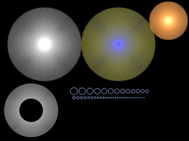
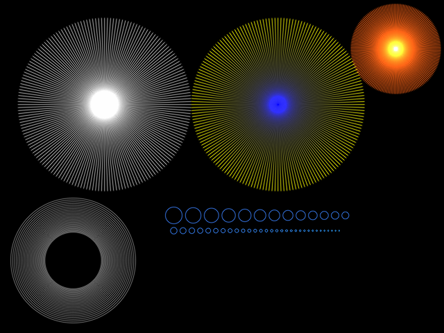
- presentationgpugems-gammgammasRGBwebGL sRGB extensionwebGL
- The solution to the problems stated is Gamma Correction.
- We want to compute our renderings in a linear space. we want to compensate for the power curve of the monitors.
- at its simplest the gamma correction function would be like display channel value=(computed channel value)^(1/2.2)
- 2.2 is the gamma correction value.
- 3JS has gamma correction built in
- when we watcha ta color swatch or a texture on the screen we are seeing the monitors power curve version of the data. if we want to use this data when computing lighting effects, we have to raise each channels val to a power of 2.2 before using it for anything computed channel value = (input texture Value)^2.2. anything like mipmaps or making images. 3js makes on the fly approximation sqwuaring color when it is sampled. To sum up what we see on screen is based in the power curve. to use it in our computation we raise it to 2.2(renderer.gammaInput=true;). to put our computations on screen we raie it to 1/2.2(renderer.gammaOutput=true)
- tutorialdemotutorial1tutorial2webgl filterimageprocweblumaluminance
- we havent talked about texture access in fragment shaders.
- we can access textures in fragment shaders
vec 4 texelColor = texture2D(map, vUv); - the theory of sampling and filtering is the same like in normal 3JS code. the rest is stting up the texture access. in shader we use the texture 2D function. this gives the color of the texture to use it in the shader. there are >40 shaders that use texture access in 3JS. they are in WebGLShaders.js
- another function is textureCube for cubemaps which takes a 3D direction as input.
vec4 cubeColor = textureCube( tCube,
		vec3(-vReflect.x, y.Reflect.y));
- many of the rest of the shaders perform image processing, where image pixels are used to form another image. e.g we want to form a grayscale image from a color image. the equation is luminance=0.212671R+0.715160G+0.072169B this equation uses linearized colors and luminance is intensity for grayscale.
- another equation for luma LUMA=0.30R+0.59G+0.11B for when the inputs are non gamma corrected.
- we can assume that we can add these formulasa as a final step in fragment shader. hoowever alpha channel is a problem. this is a post process. we want to convert to grayscale after the scen is rendered. but then its too late. the image is already on screen.
- but we can send an image off screen and have it become a texture. this is called offscreen texture or pixel buffer or render target.
- this texture is not a typical texture is not a powers of 2. it is not normally 512by512 or something to use on a mipmap chain
- our goal is to perform image processing on this so-called texture. we want for our example to read a pixel from this texture and convert it t gray.
- we would like to read a texel process it and spit it as apixel. but GPU is optimized fro triangles and textures
- how we use this texture is to draw a single rectangle with u/v coords that fills the screen. (screen filling quad). the u, v vals are used in fragment shader to precicelly grab a single texel that corresponds to our final output pixel on screen.
- maybe it seems ineficient but is fast ienought to allow multiple passed to be done per frame.
- in 3JS the EffectComposer class lets us create and chain different passes together with just a few lines of code
- for our grayscale post process our code is below it contains a vertex and fragment shader follwoing the logic abopve of a single square texture
// vertex shader
varying vec2 vUv;

void main(){
	vUv = uv;
	gl_position = projectionMatrix * modelViewMatrix * vec4(position,1.0);
}

uniform sampler2D tDiffuse;
varying vec2 vUv;
// fragment shader
void main() {
	vec4 cTextureScreen = texture2D(tDiffuse, vUv);

	// luma for non-gam-corrected computations
	vec3 = lumaColor = vec3(
			cTextureScreen.r * 0.3 +
			cTextureScreen.g * 0.59 +
			cTextureScreen.b * 0.11
		);

	gl_FragColor.rgb = vec4(lumaCOlor, 1.0);
}
- the vertex shader copies the u,v val and projects the screen filling quad to clip coordinates
- the whole pointof rendering teh rectangle is to force fragment shader to evaluate at every pixel
- the fragment shader code is simple. the texture is accessed by screen loc, so each texel is associated to the output pixel. we use the color of the texel to compute grayscale coloe. the color is saved to fragcolor and we are done
- we can stack postprocessing. e.g blurrign can be done in 2 stages. horizontal and vertical. multiple passes canbe memory efficient. sometimes the image is pingponged between post processing passes.
- we can do gamma correction as post process. it is a problem to do gamma correction if we have just 8 bits per channel. gamma correcting a 0-255 val and converting back to hex lower the resolution to 184 unique vals so we lose resolution
- code to calculate
var count = 0;
var prev = -1;
for(var i=0;i<256;i++) {
	var inFloat = Math.pow(i/255,1/2.2);
	var found = Math.round(infloat*255);
	console.log("For" + i + "gamma corrected: "+inFLoat+", channel "+ found);
	// if this next val doesnt match previous note itis a channel that is used
	if(found !== prev) {++count;}
	prev=found;
} console.log("different levels output: "+count);
- this loss of resolution causes banding
- Blurring Image (image processing so fragment shader)
- Changing an objects shape (vertex shader)
- evaluating an illumination model (both)
- performing gouraud interpolation (n rasterization so none)
- we will implement a flashlight effect. currently the effect is not realistic as light does not move around
// flashlight: is XY point in camera space inside radius?
if (length(vViewPosition.xy) > uFlashRadius) {
	return;
}
- the code above is added to fragment shader. the vViewPosition is the location of surface in view sspace. actually this is the position negated. as viewspace is looking down the negative z axis and x and y are 0 at the center of the screen, flashlight always shines in the middle. we return early if the surface is outside the flashlight radius so that only ambient contribution lights the object.
- we have added uniform vec2 uFlashOffset a 2 eleemnt vector that gives the center point of the flashlight. it is connected to gui sliders but the shader ignores it. it is our task to use it.
- if the x,y view position in this location are close enough together the flashlight must illuminate the surface
	// flashlight: is XY point in camera space inside radius?
	// Student: compare view position to uFlashOffset and see
	// if distance between the two is inside uFlashRadius
	if ( distance(vViewPosition.xy,uFlashOffset) > uFlashRadius) {
		return;
	}
- in this excercise we start with a square tesselated into a grid of smaller squares, this grid allows us to deform the surface. Deformation happens in the vertex shader. What we have to do is modify the incoming vertex position
varying vec3 vNormal;
varying vec3 vViewPosition;

uniform float uSphereRadius2; //squared

void main() {
	gl_Position = projectionMatrix * modelViewMatrix * vec4(position, 1.0);
	vNormal = normalize(normalMatrix * normal);
	vec4 mvPosition - modelViewMatrix * vec4(position,1.0);
	vViewPosition = -mvPosition.xyz;
}
- as this is an innput var we have to copy it to a temp var and mod this instead. we need to use this temp in all shader istead of position
- to modify the positon we have to use this formula
ZPOS = sqrt(uSphereRadius2 - XPOS^2 - YPOS^2) - sqrt(uSphereRadius2). the first half of the func finds a poin on the sphere. the second translates the whole object by a constant amount so it stays in view. the uSphereRadius2 is a var passed by the main program. its the square of the radius set with a gui slider. XPOS, YPOS< ZPOS are the position coordinates. * to access an individual val of a vector use vector.x or y or z. - when we are done we should see something like a surface part of a sphere.
- solution
void main() {
	// Student: modify position. You'll need to copy it to a
	// temporary vector and modify the temporary.
	vec3 tempPosition = position;
	// ZPOS = sqrt(uSphereRadius2 - XPOS^2 - YPOS^2) -  sqrt(uSphereRadius2)
	tempPosition.z = sqrt(uSphereRadius2 - (tempPosition.x*tempPosition.x) - (tempPosition.y*tempPosition.y)) - sqrt(uSphereRadius2);
	// Don't forget to use this temporary in the rest of the shader.
	gl_Position = projectionMatrix * modelViewMatrix * vec4( tempPosition, 1.0 );
	vNormal = normalize( normalMatrix * normal );
	vec4 mvPosition = modelViewMatrix * vec4( tempPosition, 1.0 );
	vViewPosition = -mvPosition.xyz;
}
- illumination is not good because vertex shader did not change shading normals
- tutorialwater demodemo
- in addition to computing a new position to form a piece of sphere surface, we have to set the normal to look right. for a sphere centered atr the origin this is straightforward. normal and vectyor to the point match.
- we take the solutionb from the previous problem and chang ethe shading normal to point at the right direction. we again have to use a temporary normal.we dont have to normalize it as this will be done in the fragment shader.
void main() {
	// Student: modify position. You'll need to copy it to a
	// temporary vector and modify the temporary.
	vec3 tempPosition = position;
	vec3 tempNormal = normal;
	// ZPOS = sqrt(uSphereRadius2 - XPOS^2 - YPOS^2) -  sqrt(uSphereRadius2)
	tempPosition.z = sqrt(uSphereRadius2 - (tempPosition.x*tempPosition.x) - (tempPosition.y*tempPosition.y));
	tempNormal = tempPosition;
	tempPosition.z -= sqrt(uSphereRadius2);
	// Don't forget to use this temporary in the rest of the shader.
	gl_Position = projectionMatrix * modelViewMatrix * vec4( tempPosition, 1.0 );
	vNormal = normalize( normalMatrix * tempNormal );
	vec4 mvPosition = modelViewMatrix * vec4( tempPosition, 1.0 );
	vViewPosition = -mvPosition.xyz;
}
- we first set the z on the sphere. set the shading normal and then and AFTER we Offset the surface so the center stays in view
- [thresholding](https://en.wikipedia.org/wiki/Thresholding_(image_processing)
- beyond prog shading
- One thing about Blinn-Phong Specular Highlighting is that the drop-off is always gradual around the fringe. even if highlight is at max we still see the dropoff. we also cant control the width of the highlight. Our task in this exercise is to threshold the blinn-phong specular term if specular < uDropoff set it to 0 else 1 after computing the specular contribution
	// Student: add test here, when specular < uDropoff, set to 0.0, else to 1.0
	if (specular < uDropoff) {
		specular = 0.0;
	} else {
		specular = 1.0;
	}
- The article that talks about wrap lighting is Real-Time Approximations to Subsurface Scattering.
- a cheap technique to give a material a slightly different look is to use wrap lighting. Like we did with Toon Rendering, we shifted where the diffuse term goes from light to dark. we can do the same shift with diffuse term but not just thresholding the bal.
- our task is to change the diffuse term to be this warp lighting term max of (NdotL + Wrap)/(1+wrap) and 0
	// Diffuse: N * L.
	// Student: modify diffuse here with wrap equation. Wrap is passed in as "uWrap".
	float diffuse = max( (dot( normal, lVector)+uWrap)/(1.0+uWrap), 0.0 );
- minecraft vogel demo blog git
- dat.gui
- chase camera multicam demo
- in 3JS its easy to hook up events from mouse, keys etc (see Javascript)
- up to now we had almost no interaction with the virtual world. the only direction was to move the camera.
- with animation we add a forth dimension . time
- w3 dom events
- look in three.js repo for addEventListener
- file search utils
- direct interaction is handled using events. event is generated on user interaction or by the system.
- mouse click event
document.addEventListener('mousedown', onDocumentMouseDown, false);onDocumentMouseDown is an async callback function
function onDocumentMouseDown(event) {
	event.preventDefault(); // disables default behaviour like page refresh
}
- three.js demo picking blocks. non webgl demo
function onDocumentMouseDown(event) {
	var mouseVector = new THREE.Vector3(
		2* (event.clientX / canvasWidth) -1,
		1 - 2 * (event.clientY / canvasHeight));
	var projector = new THREE.Projector();
	var raycaster = projector.pickingRay(mouseVector.clone(), camera);
}
- the previous demo performed 2 actions.
- selecting the object clicked on
- and if an object was found it was modified and the point clicked on was highlighted.
- picking objects on the screen with a mouse is simple in 3JS.
- in the code above we see the first half ogf the event callback that sets up to do the picking.
- the code fires a ray from the eye into the world. this is a common way to do picking.
- WebGL is focused on rendering. has no real support for interaction or picking. the program will figure out.
- To form a ray from the eye through the screen we need two points. first is the eye position in the world space. the second is a point on screen wherever the user clicked the mouse. what we want to know is THIS POINTS Location in WORLD SPACE.
- To do so we need to travel upstream back along the chain of transformations => W P V ->world<- M Object. Window coordinates to normalized device coordinates to view to WORLD Coordiantes. 3JS makes this easy
- The 2D point from the MouseEvent is a document object model screen coordinate. this is like a WebGL Window Coordinate only that y 0,0 is on the tope left edge of the screen
- THe mouse vector code converts from this screen into normalized device coordinates NDC which goes from -1 to 1 in x and y. Z val does not really matter. any value of z from -1 to 1 will form a point on the ray.
- We next create a projector object. its beeter to create this object at initialization. the final line at our code snippet takes the NDC coordinate and forms a rayCaster object from it.
- Raycasting is like raytracing except that we only trace rays from the eye into the scene and no further. no new rays are spawn from interections.
- when we have the raycaster object we can perform picking or hit testing. see code below
// hit testing
var intersects = raycaster.intersectObjects(objects);
if(intersects.length > 0) {
	intersects[0].object.material.color.setRGB(Math.random(), Math.random(),Math.random());
	// add sphere
	var sphere = new THREE.Mesh( sphereGeom, sphereMaterial);
	sphere.position = intersects[0].point;
	scene.add(sphere);
}
- we feed a list of objects to the raycaster and it returns an array of intersections. the intersections are listed front to back.
- the intersection has info about the ray hit: object, face, faceIndex, distance, point. we use object parameter to change material to randomcolor. to show the point we draw a sphere around it.
- once we pick an object we might want to drag it to a new position. it is a more difficult process as we have to respond to mouse move and mouse self events.
- the main question of dragging in 3D space is how to constrain the third dimension. one approach is to constrain the movement to be parallel to the screen surface. the other method is to limit the movement of the objecct to be on a world plane or other geometry on scene. for example. if you drag a handle on a face of a box to resize it we limit interaction to be along the faces normal direction
- beyond the keyboard and mouse combinations (double click, shift, ctrl keys) there are also different forms of selection. in areas like real time strategy games and CAD programs we can select a set of object by drawing a rectangle around them on screen.
- this kind of selection is done by fonding which objects are fully or partially inside whats essentially a smaller frustum on the screen.
- lass selection lets us draw arbitrary shape . these are not part of 3JS.
- we dont have to select visible pobjects . eg to position directinal light we might put an invisible sphere in the scene and make it selectable. when a user clicks on the sphere determines apoint in space(where light comes from)
- end of interaction (wtf?) now we wil talk abut animation
- requestAnimationFrame
- we have initialized our scene with lights objects and camera. naturally next step is to render.
renderer.render(scene,camera); - its not uncommon to render the scene once at initialization. sometimes we need to update the scene at runtime.
- once scen is setup calling animate function does the trick with the requestAnimateFrame() method.
function animate() {
	windw.requestAnimationFrame(animate);
	render();
}
- this method will start up rendering when it makes sense to. it also eases the GPU usage. if we switch tabs in browser it will pause the program. animate emthod calls render() to render the scene and much more.
function render() {
	var delta = clock.getDelta();
	cameraControls.update(delta);
	renderer.render(scene,camera);
}
- in render() we put code that does changes before rendering the scene, chang eposition of a ball, use a gui param etc.
-
Lets get animating, putting sthing in the render method to make our drnk bird move.
-
geometry has been organized to facilitate animation. bird has been split in two parts. the static support(legs feet prg) and the animated bird (body head hat). the bodyhead is a new Object3D.
-
next we do sthing javascript allows . add a param at an object at runtime. we do this to access it in render.
var bodyhead = new THREE.Object3D();
bodyhead.add(body);
bodyhead.add(head);

// add field fror animated part, for simplicity
bbird.animated = bodyhead;

bbird.add(support);
bbird.add(bodyhead);
- if we do spelling errors while assigning new params we get nasty bugs.
- in the code below animation happens. we want to rotate the body around the z axis the crossbar. we use tiltDirection param. it can be 1 or -1. if it is 1 the rotation increases by a small amount at each render. when it reaches max angle direction changes to -1 and rotation decreases by an amount.
var titltDirection = 1;

function render(){
	bird.animated.rotation.z += tiltDirection * 0.5 * Math.PI/180;
	if (bird.animated.rotation.z > 103 * Math.PI/180){
		// backwards
		tiltDirection = -1;
		bird.animated.rotation.z = 2*(103*Math.PI/180) -bird.animated.rotation.z;
	} else if (bird.animated.rotation.z < -22 * Math.PI/180){
		// forward
		tiltDirection = 1;
		bird.animated.rotation.z = 2*(-22*Math.PI/180) -bird.animated.rotation.z;
	}

	renderer.render(scene,camera);
}
- we would like to see the bird rotating around the crossbar. but with the code above the bird rotates around the origin. we havent set a pivot point for the body at the crossbar.
- our task in this exercise is to set the pivot point for the head and body of the drinking bird to be at the crossbar. this has to do with the order of transforms, translate and then rotate. but its not that simple. birds body and head are in correct spot. what if we move the fram of reference to the crossbar. then put all in an object and move the parent to the location after doing the rotation
- our task is to modify the createDrinkingBird method so that the pivot is correct, we get the pivot height. also it should take us just 3 lines of code to do it
- order of operations: translate body and head so that crossbar is at origin -> rotate (done with render() method) and then translate body and head back to start
- we might want to add an intermediate object a bodyhead. its cleaner to apply a translation to this object
	// Student: change pivot point
	// pivotHeight is the height of the crossbar
	var pivotHeight = 360;
	bodyhead.position.y = -pivotHeight;
	var animated = new THREE.Object3D();
	animated.add(bodyhead);
	// add field for animated part, for simplicity
	bbird.animated = animated;
	animated.position.y = +pivotHeight;
	bbird.add(support);
	bbird.add(animated);
- we translate
- then add to a new object se this as animated and translate it back
- in the previous demo we base aour animation on the frames rendered. each frame rotates the bird half a degree. so depnding on the framerate on each machine the motion looks different. if we say sync animation with voice or music this does not work
- we want to use real time to decide rotation
- the funstion getDelta() returns the ms that elapsed since the clock was created or last time getDelta() was called
var clock new THREE.Clock();

function render() {
	var delta = clock.getDelta();
};
- so taking the time lapse between frames we can take them into account in the angle calculation and move from a fixed step size
bird.animated.rotation.z += tiltDirection * 0.5 *Math.PI/180;to a clock controlled step (angle)bird.animated.rotation.z = tiltDirection*30*delta*Math.PI/180; - if we hide the page and open later the delta is huge and animation gets craz
- the
getElapsedTime() returns the elapsed time since the creation of clock. we want 30 degrees per second so we multiply it by 30. we have 250 degrees of freedom so we dive this val with modulo 250
var angle = (30*clock.getElapsedTime()%250;
if(angle < 125) {
		// go from -22 to 103 degrees
		bird.animated.rotation.z = (angle - 22)*Math.PI/180;
	} else {
		// go back from 103 to -22 degrees
		bird.animated.rotation.z = ((250 - angle) - 22)*Math.PI/180;
	}
- even for a single angle of freedom like in the drinking bird it is difficult to do motion capture. motion capture is done tracking points (like balls) with various special cameras. the transformmatrixes that are derived are applied to 3d objects
- tween.js
- demo
- blender export
- greensock animation lib
- wiki
- math for game prog
- threefab
- export blender to threefab
- tool
- the principle of keyframing is this. save the state of an object at various times and interpolate between these
- if i have an object at postionA at Time=A and positionB at Time=B the time function of its position between timea and b is position(time=T)=(B-T)/(B-A) * positionA + (T-A)/(B_A) * positionB
- the process of generatiing these frames between the key frames is called tweening
- with the drinkbird we can do the same say at A is at the Down position and B is in Up position abd say it takes 2sec to go up (A-B) and 3sec to go down (B-A). we canno concider the second pass from A down move as A as the ya re differently placed in time . we call it C. between C and A we have a pause of 0.5s.so A-B=2s B-C=3s C-A=0.5s A and C are down and B is Up . we make a graph of angle vs Time. what we see is that the pass from B is abnormal is a peak. is not natural. this is the effect of linear interpolation
- to make it natural and smooth we use spline curves (tween.min.js)
- using threefab we can see how with a few keyframes we can achieve elaborate motions
- demo code using tween
// TWEEN
	// tutorial: http://learningthreejs.com/blog/2011/08/17/tweenjs-for-smooth-animation/
	var updateBird = function(){
		bird.animated.rotation.z = current.z;
	};
	var current = { z: 0 };

	var drinkingRotation = { z: 103 * Math.PI/180 };
	var backRotation = { z: -22 * Math.PI/180 };
	var wobbleRotation = { z: 22 * Math.PI/180 };
	var back2Rotation = { z: -8 * Math.PI/180 };

	var tweenForward = new TWEEN.Tween(current).to(drinkingRotation, 3000 );
	tweenForward.onUpdate(updateBird);
	tweenForward.easing(TWEEN.Easing.Cubic.In);

	// don't do anything: drink
	var tweenPause = new TWEEN.Tween(current).to(drinkingRotation, 500 );
	tweenPause.onUpdate(updateBird);

	var tweenBackward = new TWEEN.Tween(current).to(backRotation, 1200);
	tweenBackward.onUpdate(updateBird);
	tweenBackward.easing(TWEEN.Easing.Quadratic.InOut);

	var tweenWobble = new TWEEN.Tween(current).to(wobbleRotation, 1000);
	tweenWobble.onUpdate(updateBird);
	tweenWobble.easing(TWEEN.Easing.Quadratic.InOut);

	var tweenBackward2 = new TWEEN.Tween(current).to(back2Rotation, 900);
	tweenBackward2.onUpdate(updateBird);
	tweenBackward2.easing(TWEEN.Easing.Quadratic.InOut);

	// have one call the other next, and back
	tweenForward.chain( tweenPause );
	tweenPause.chain( tweenBackward );
	tweenBackward.chain( tweenWobble );
	tweenWobble.chain( tweenBackward2 );
	tweenBackward2.chain( tweenForward );

	// get this chain going
	tweenForward.start();
- tutorial
- is like a flip book when we draw an image in each page and we flip through them. also we can do it by transforming texture coordinates
-
our job is to use the texture transform feature to animate water as shown moving top to bottom, rate of movement is 1s per copy of texture, when the txeture repeat is 3 a texture will take 3s to move from top to bottom.
-
our time loop much bebased on thelapsed time in real world
-
my solution
texture[effectController.mtlName].offset.set(0,clock.getElapsedTime()*effectController.repeat);
*teacher solution (think of modulo based on texture size)
// add some wobble texture[effectController.mtlName].offset.set( 0.2Math.sin(2time), time ); texture[effectController.mtlName].repeat.set( effectController.repeat, effectController.repeat/3 );
- slerping
- rotations
- quaternion represents orientation of an object, how is rotated
- they do the same as angle rotations. they rotate a model around a givenaxis by an angle
- they are used a lot in animation because we can interpolate easily between one orientation and another.
- say we have to vectors poking through the sphere from the origin
- if we use euler angles ther is gimbal lock as one angle is applied before the other. euler angles are terrible for interpolation aroundan arbitrary axis especially if the change is large
- if we use axis/angle scheme (whole angle in 4 frames) we would go 1/4 angle anf formm new matrix. each number needs trogonometric functions as we have rotation over 2 axis
- with quaternions we do it easily using axis-angle like matrixes that contain 4 values , numbers )
- when we interpolate around an axis is called a SLERP (spherical linear interpolation). we move from 1 point in the sphere to another in a linerar fashion
- in 3JS for angle/axis rotations we need traslation and scaling matrixes in the pipline. quaternions in 3js can be combined with other trasformation matrices . with the difference that quaternions have only 5 values
- they are used in flycontrols.js
- when we use quaternions with camera the camera up vector is not maintened and need to reorient
- 3JS skinning
- skinning2
- skinnign3
- demo
- tutorial
- a robot model has rigid elements that do not change over time like forearm upper arm. at the joint the objects are clearly seperate.
- at the joint we need to put some skin like some triangles connecting the two rigid pieces. as the joint beds these triangles deform and stretch always attached to the two arm pieces.
- this doesnt look good,we would like a flexible tube that bends but keeps its shape. say we add such a joint with 3 cylinders one after the other. the uestion is how to move the cylinders as the joint bends.
- solution is simple. each vertex is assigned a weight. the weight is how each rigig part position affects the vertex
- this modelling process of adding polygons and assigning weights is called skinning or verrtex blending.
- the rigid parts of the body are called bones. the bones combined form a skeleton so the whole area is called skeletal animation
- this method has flaws like the inner arm where vertexes bend inwards
- a vertex can be influences by more thins than 2 bones
- ginger demo
- tutorial
- skiining morphing
- wiki
- loader
- webgl loader
- 3js faq
- morphing is the process of changing from one model to another model. if model differ considerably it is a difficult problem to solve
- it simple to interpolate between 2 models with the same number of vertices. linear interpolation between these two meshes is trivial
- A more general approach uses what is called morph targets or key poses. e.g a smile can be neutral, happy or sad. to go from one to other we interpolate. key poses are like key frames. morph targets can be combined. skinned targets cab be morphed.
- it is laborious to create morph targets. the process of setting characters animation cotnrols is called Rigging. needs skill and time to do it. this works is always done with special SW. morphing stretches the GPU
- interactive #d is used extensively in previsualization, in setting up the scen, (cameras objects, light in a virtual world). Interview with Third Floor (Previsualization company). They were founded for Star Wars III. the capture their motion capture suit interview
- they build a simple character
- they rig it with their riggin system
- there is no skinning to keep it fast
- they set animation seq or do it with motion capture (they multiply the char)
- they build location to large scale
- they add effects (e.g simple images but scaled correctly)
- they start controlling the camera (pan tilt, dolly shot), they add hand effect
- they add green screen scales properly
- they give a film plan to produces that follows how this was digitally filmed in virtual world
- tutorial
- tutorial2
- 3js example1
- 3js example2
- 500k demo
- puff
- fuzzy particles
- particles can be used for all sorts of animations. objects can be formd of particles instead of triangles
- cannon.js
- Phsijs
- tutorial
- raycasting for collision
- RT rendering
- collision detection is detection when 2 objects move and start to overlap
- shooting rays from users location and finding intersections distance will reveal wheter users position should be readjusted
- when we have many objects brutforce means comapare everything with everything on scene
- smart collistion detection is about datastraucts that quickly call out possible collisions in a frame
- next thing is what to do if we find out collision. it has to do with object spped and elasticity
- physical sim
- phys anumation
- for simple physic simulations keyfframing suffice (bounsing ball)
- for complex we go to simulation
- nucleus dynamic solver
- ncloth maya
- cloth
- simulations use physics formulas found in physics and engineering textbooks
- flow
- friction
- drag
- elasticity
- tension
- turbulence
- heat transfer
- drag, lift, stretch
- simulations work by a small timeframe, smaller than the time represented by a frame, small steps, time after time.
- if interactive speed is not needed time slices can be very small
- for interactive rendering we do simplification
- a cloth can be a realtime simulatio (created -viewed). complex ones can be stored at object location, these stored locations can be treated as morph targets
- Frwning troll => morph target
- avalanche => simulation
- fymnastic flip => motion capture
- show right hand rule with hand => sceletal animation
- demo
- fps meter
- book
- virtual textures
- quadrics
- meshlab
- how to change object representatin as its size on screen changes
- perform VS quality tradeoff
- affects meshes and textures
- textures: down sample (various versions prder of 2mip chain )
- memory constrains
- smaller object? simplify illumination equation
- object smaller? displacement map => normal map => nop map
- object smaller ? fewer vertexes (decimation algorithm)
- if models differ considerabley we see a pop
- LoD method, vertex moves along an edge to be at the same loc as another vertex (thgen store only 1) we save 3 edges, 2 faces => Euler -Poincare Formula V+F-E+2G=2 (V:Vertices, F:faces, E:edges, G:genus) genus is number of holes in object. sphere, cude (genus 0) donut (genus 1). in our example if we create avertex in agenus 0 obj we have 1 + 2 -3 + 0 no holes created . the delta is 0 so the formula holds always
- Performance per Watt