The WeatherStation machine is designed to display todays weather by retrieving information from a forecast API called "OpenWeather". What makes it special is that the weather is shown through a window where two rotating wheels create a picture of what the weather is going to look like by overlaping. In addition to that, a RGB LED is installed inside the machine and programmed to change color according to the time of the day, going from a deep blue for midnight to a violet blue for sunset, through different shades of light blue and yellow for the brightest hours of the day. For a more accurate forecast, at the bottom a LCD Display presents additional information, such as humidity, termperature, feels-like temperature, location and time.
- 2 ESP32 Wi-Fi & Bluetooth MCU (DOIT-V1-DEVKIT)
- RGB LED
- ILI9341 TFT LCD Display
- 2 28BYJ-48 Stepper Motor + ULN2003 Motor Driver
- 2 large gear wheels with weather drawings (?)
- 2 smaller gears to transmit the rotation
- a structure to hold everything toghether
To control the stepper motors we used an Arduino built-in library called "Stepper.h", that provides easy funztions to move the motor by a defined number of steps. The 28BYJ-48 Stepper Motor has a stride angle of 5.625°, so it needs 682 steps to rotate of 120°. But in our case, the motion isn't directly transmitted to the main wheel, but through a smaller gear. This means that to get a rotation of 120° it is necessary to use the gear ratio:

To interface ESP32 with the stepper motor, we use the ULN2003 motor driver that presents a connector to attach the motor, four input pins that are connected to 4 General Purpose I/O pins of the board, and two power supply pins connected to the Vin and GND pins of the ESP32. This needs to be done for each stepper motor.
To use the display we used an Arduino built-in library called "TFT_eSPI.h", which provide functions to draw and write on the display, with the possibility to set the colors. The ILI9341 display we choose is 2.8" with a resolution of 240x320 pixels. The display communicate with the ESP32 through SPI protocol, 5 input pins are connected to 5 General Purpose I/O pins on the board, and three power supply pins connected to the Vin, 3v3 and GND of the ESP32.

IMPORTANT: LED pin should be connected to a power supply pin instead of D32
All the configuration of the led can be found in the folder src in a custom library called "ledcrl.h". There, we defined a function to setup the led and one to choose the right color according with the daytime. We realized that function by defining a matrix with a predefined number of (r,g,b) values, based on the time (both hours and minutes are required), the right color is selected and displayed by the led. It is possbile to change the pin configuration chosen by default, but it is important to connect one pin with the ground, one with Vin and one with a MOSI pin (deafult 12)
In the folder svg_files you can find all the models of the structure we created for our project. To make our structure and disks we used a laser cutting machine in FabLab, which is a workshop situaded in the University of Trento that offers digital fabrication tools
To devolop the project we have decided to use Platform.IO, an extension of Visual Studio Code that has all the functionality of Arduino IDE and an easier interface, in particular for the creation of structured projects with many files. Besides this, it is possible to obtain the same result in Arduino IDE, manually manging all the project structure. In the repository there are two different projects, one for each ESP32. This choice has been made because the LCD screen requires many pins and memory to work properly. To handle information exchange between the two ESP32s and the PC, we choose to use MQTT protocol, for sending information from PC to ESP32 (and to monitor that messages are exchanging correctly) we used the MQTTX interface. Since we used many external libraries, it is possible to install it thanks to the Platform.IO manager using the following commands in the platform control cli
Weather station
pio pkg install --library "fastled/FastLED@^3.5.0"
pio pkg install --library "arduino-libraries/Stepper@^1.1.3"
pio pkg install --library "bblanchon/ArduinoJson@^6.20.1"
pio pkg install --library "knolleary/PubSubClient@^2.8"
Display controller
pio pkg install --library "bodmer/TFT_eSPI@^2.5.2"
pio pkg install --library "knolleary/PubSubClient@^2.8"
pio pkg install --library "bblanchon/ArduinoJson@^6.20.1" This part of the project handles the MQTT message received from PC to esp32, show the informations about weather on display and send the information to the other esp32.
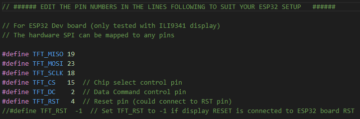
First to make sure that the display works set up the pins properly by:
- Display_Controller -> .pio -> libdeps -> TFT_eSPI -> User_Setup.h
- Uncomment (if commented) "#define ILI9341_DRIVER" and comment all the others drivers setup
- Uncomment (if commented) and set the lines
For receiving and sending information (respectively from PC and to the other ESP32) we decided to use a MQTT broker. In particular we decided to use HiveMQ MQTT broker, however it should work even using others MQTT brokers. Remember to set up the following macros in the "MQTT.h" file:
TOPIC_CITYname of the topic in the MQTT broker where you receive the city name from PCTOPIC_WEATHERname of the topic in the MQTT broker where you send the actual weather and time to the other ESP32SERVERname of the broker (can be found easily on the official site of the MQTT broker you choose or it's possible to create a private one)CLIENTname of the connection to receive message on MQTTX
Now you have to set up the broker trough MQTTX. Open the desktop app, go to the first section in the slidebar on the left and click the botton "+"
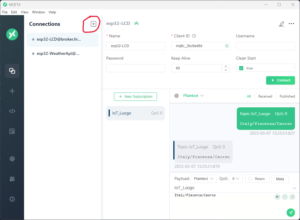
Now click on "New Connection" and give a name to your connection and change the second field of the voice "Host" with "broker.hivemq.com" (or the name of yout broker, it must be the same used for SERVER).
Then click on the newly created connection and next on the green button "Connect" to open the connection with the broker.
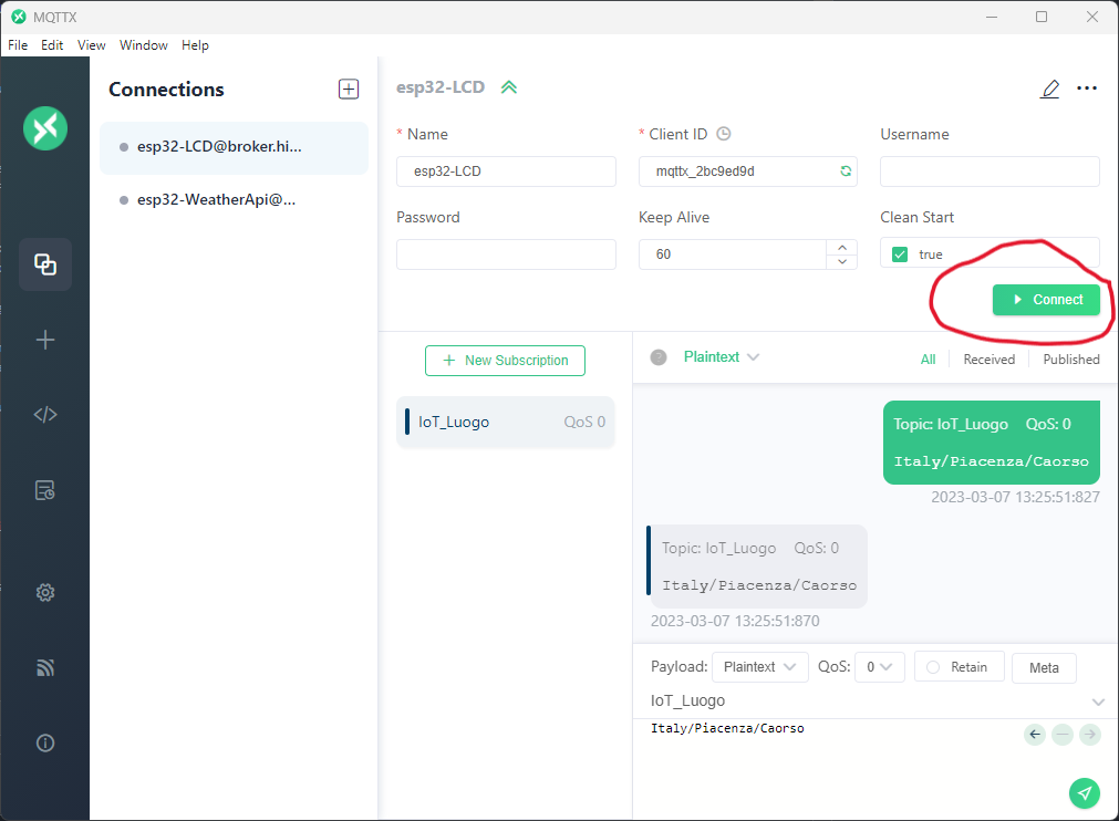
After that click the green button "+ New Subscription" to create a new topic, and choose the name of the topic.
BE CAREFUL! The topics will be public so everyone can access to it (and publish on or subscribe to some topics), to avoid this problem make sure to give an uncommon and/or complex name.
Now you can send message to every device (connection) subscribed to a topic, by writing in the white area under the name of the topic you're writing in and clicking the green arrow on the right.
Initialize the communication with the MQTT broker
void MQTT_inizialization()
{
    Serial.println("MQTT inizialing");
    client.setServer(SERVER, 1883);
    client.setCallback(callback);
}
Try to connect to the client (connection), if it succeed it subscribe to TOPIC_CITY and return true, elsewhere return false
boolean reconnect()
{
    if (client.connect(CLIENT))
    {
        Serial.println("connected to client");
        // ... and resubscribe
        client.subscribe(TOPIC_CITY);
    }
    return client.connected();
}
It's the handler of MQTT message, every time a message in the topic TOPIC_CITY is published, the callback function will save the message (containing the city name) and send a new HTPP request, asking for data about the city's weather.
void callback(char *topic, byte *payload, unsigned int length)
{
    Serial.println("MQTT message received");
    if (strcmp(topic, TOPIC_CITY) == 0)
    {
        char string[length + 1];
        // handle message arrived
        for (int i = 0; i < length; i++)
        {
            // convert the payload from byte to char and save it as a string
            string[i] = (char)payload[i];
        }
        string[length] = '\0';
        setCity(string);   // set city name
        setReqBool(true);  // send a new request
    }
}The API used in this project can be found at https://www.weatherapi.com. To use it, it is important to remember to set un the internet connection to enable the requests to the api.
Remember to set up the following macros in the "api.h" file:
MYSSIDWiFi namePASS_WIFIWiFi passwordCONST_DELAY_APItime to pass between a request sending and another without receiving new inputs (by default 30 minutes)
The request to the api are performed by this part of the function "make_request()", that can be found in the library "api.h". These requests are done creating a proper GET HTTP request to the web server of the API.
if(client.connected()){
        client.println("GET " PATH "?key=" APIKEY "&q=" TRENT " HTTP/1.0");
        client.println("Host: " HOST);
        client.println("Connection: close");
        client.println();
        Serial.println("request made");
        while(!client.available()){
      //Serial.println("Waiting for client");
    }
Is is important to consider that the data requested are given in the response of the HTTP request. For this reason the headers are skipped, the data are saved in a "DinamicJsonDocument" and then deserialized in order to return only the relevant information. The data received will be displayed on the LCD screen and also sent thanks to the MQTT server to the other ESP32 in order to move the wheels according to them.
This part of the project controls the ESP responsable for the rotation of the wheels and the correct illumination of the led. The information about what to display is given by the other ESP through a MQTT message, that is properly parsed in order to have the right information. The info passed consist of time and weather.
For the ESP32 to interface with the stepper motor, we used a ULN2003 motor driver for each moter. The driver comes with a connector that simplifies the connection with the motor itself, 4 input pins that control the coils that make the stepper motor move and two pins to connect power supply and ground. The six pins in the driver need to be wired to the ESP32, the file weather_station/src/step.h in the github folder indicates how the pins are connected. However, since we had to power the LED and no pins left (ESP32 has only two VCC and GND pins) it was necessary to use a breadboard. In addition to GND and VCC pins, the LED needs an additional pin which controls color. For this purpose, weather_station/src/ledcrl.cpp indicates the pin used for LED control.

Once received the information, they are elaborated thanks to a Finite State Machine that takes as input a structure composed of boolean values describing the weather taken from the open weather api. This object is created with the data passed using the MQTT message after parsing. The FSM gives the input and the direction of rotation of the wheels cousing the motion.
To memorize the state of the wheels in case of disconnection, we used the eeprom library to write the status value into memory, and read it when powering on, in the setup phase. We save the state of the machine after every motion of the wheels, in order to be always updated in case of disconnection. This values are read during the setup, not in every iteration of the loop. In the init_info function in rotcontrol.cpp we find the code to read the memory. We are reading two integers, one for each wheel, each one is 4 bytes long as specified in the addresses.
    EEPROM.begin(EEPROM_SIZE);
    int state_up = EEPROM.read(0); // one per wheel
    int state_down = EEPROM.read(4); // one per wheel
In the rot_control function in rotcontrol.cpp we find the code to write the state value of each wheel in memory. As said before the addresses are properly configured to contain integers.
    EEPROM.write(0, *up_state);
    EEPROM.commit();
    EEPROM.write(4, *down_state);
EEPROM.commit();The led is controlled thanks to the time returned by the MQTT message. To create the sliding of colors, we specified in the code 48 triplets of numbers, representing RGB values. The time is passed in the control_led function and set the color of the led. The functions to set up and update the led color are in ledcontrol.cpp
// set up led
    FastLED.addLeds<WS2812, DATA_PIN, RGB>(leds, NUM_LEDS);
    FastLED.setBrightness(BRIGHTNESS);
// configuration of the led
    leds[0].setRGB(lister[iter%D_NUM_COLOR][0], lister[iter%D_NUM_COLOR][1], lister[iter%D_NUM_COLOR][2]);
FastLED.show();For receiving information (from the other ESP32) we decided to use a MQTT broker. In particular we decided to use HiveMQ MQTT broker, however it should work even using others MQTT brokers. Remember to set up the following macros in the "MQTT.h" file:
TOPIC_WEATHERname of the topic in the MQTT broker where you receive the actual weather and time from the other ESP32SERVERname of the broker (see section MQTT of Display Controller above)CLIENTname of the connection to send message on MQTTXMYSSIDWiFi namePASS_WIFIWiFi password
The setup on MQTTX is identical to the one mentioned above
It's the handler of MQTT message, every time a message in the topic TOPIC_WEATHER is published, the callback function will save the message (containing the actual weather and hour), it will parse the message and call the control_led function
void callback(char *topic, byte *payload, unsigned int length)
{
    Serial.println("MQTT message received");
    if (strcmp(topic, TOPIC_WEATHER) == 0)
    {
        char string[length + 1];
        char hour[2];
        char minutes[2];
        // handle message arrived
        for (int i = 0; i < length; i++)
        {
            // converto il payload da byte a char e lo salvo su string
            string[i] = (char)payload[i];
        }
        string[length] = '\0';
        Serial.println(string);
        parseTimeAndWeather(string, hour, minutes);
        lowerCaseString(string);
        set_weather(string);
        int int_hour = atoi(hour) * 2;
        int int_min = atoi(minutes);
        if (int_min < 30)
        {
            int_min = 0;
        }
        else
        {
            int_min = 1;
        }
        control_led(int_hour + int_min);
    }
}In the testing directory are present the .ino files that can be flashed and run singularly in order to test single components. We used it in order to be sure that single components works properly.
WeatherStation Presentation - WeatherStation Video-presentation
Students: Annachiara Fortuna - Giuseppe Ostacchini - Erestina Vreto
Project for the course "Embedded Software for the Internet of Things" 2022/2023 - Kasim Sinan Yildirim
