TFmini Plus can be used in Pixhawk for the purpose of obstacle avoidance.
Firmware versions after 2.0.3 are currently supported. For versions before 2.0.3, packages can be upgraded on the official website (en.benewake.com/download).
If multiple TFmini Plus are connected, in order to prevent communication interference, it is suggested that the frame rate be set to 250 Hz, and the measured 100Hz is also available. see details in chapter 7.4 “frame rate”.
The default communication of TFmini Plus is TTL,IIC and TTL are same cable, so please set TFmini Plus to IIC communication first, see detail commands in product manual. We take two TFmini Plus as an example in this passage and set the address 0x10 and 0x11 separately. It is recommended to configure the address in serial mode.
Note: After changing to IIC mode, the UART mode can be switched back only when the switching command is sent to the TFmini Plus via the IIC communication tool. Otherwise, it cannot be switched back.
See detail cable definition in Pixhawk manual and TFmini Plus manual, we take Example for connecting Pixhawk
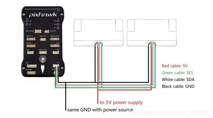
Note:
- Default cable sequence of TFmini Plus and Pixhawk are different, please change it as demand
- IIC connector should be purchased by user
- If TFmini Plus face down, please take care the distance between lens and ground should be bigger than TFmini Plus’s non-detection zone(10cm)
- If more TFmini Plus are applied, method is same.
- Power source should meet the product manual demands:5V±0.5V,bigger than 140mA*number of TFmini Plus.
Currently, the firmware version supporting TFmini Plus communication is v4.0.0. The pixhawk firmware can be obtained from the following website: http://firmware.ardupilot.org/Copter/latest./
The pixhawk firmware of version 3.6.11 also supports connection to TFmini Plus IIC, but only two connections are supported at most.
AVOID_ENABLE=3
AVOID_MARGIN=4
PRX_TYPE=4
RNGFND1_ADDR=16 [Address of #1 TFmini Plus in decimal]
RNGFND1_GNDCLEAR=15 [Unit: cm, depending upon mounting height of the module and should be bigger LiDAR than non-detection zone]
RNGFND1_MAX_CM=400 [It could be changed according to real demands but should be smaller than effective measure range of LiDAR, unit is cm]
RNGFND1_MIN_CM=30 [It could be changed according to real demands and should be bigger than LiDAR non-detection zone, unit is cm]
RNGFND1_ORIENT=0 [#1 TFmini Plus’s real orientation]
RNGFND1_TYPE=25
RNGFND2_ADDR=17 [Address of #2 TFmini Plus in decimal]
RNGFND2_GNDCLEAR=15
RNGFND2_MAX_CM=400
RNGFND2_MIN_CM=30
RNGFND2_ORIENT=25 [#2 TFmini Plus’s real orientation]
RNGFND2_TYPE=25
Upon setting of these parameters, click [Write Params] on the right of the software to finish.
If the error message “Bad Lidar Health” appears, please check if the connection is correct and the power supply is normal.
How to see the target distance from the LiDAR: press Ctrl+F button in keyboard, the following window will pop out:
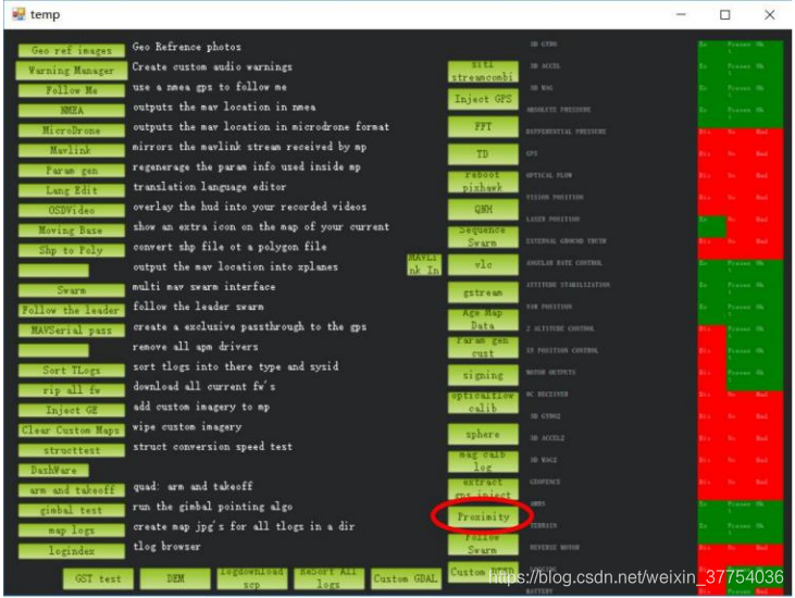
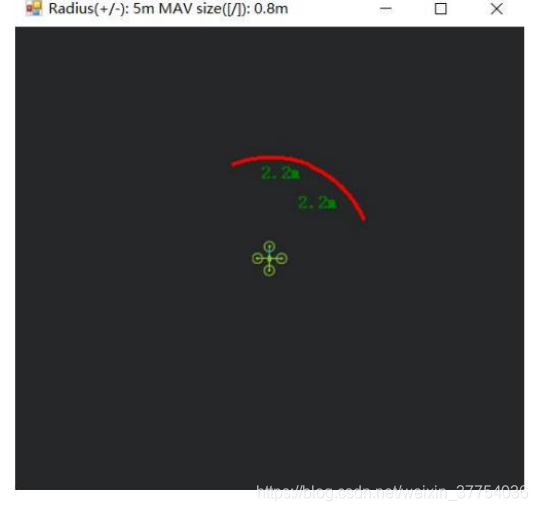
Click button Proximity, the following window will appear:
The number in green color means the distance from LiDAR in obstcle avoidance mode(the number only refresh when this window open, close, zoom in or zoom out, it doesn’t mean the real time distance from LiDAR and will not be influenced in Mission Planner version under v1.3.48, the problem could be solved by updating Mission Planner)