This repository contains a software package for performing small-signal AC analysis simulations of electrical circuits, similar to LTspice. Developed as part of a Year 1 end-of-year project, this software includes features such as parsing the netlist file, setting up the simulation, and constructing/solving the conductance matrix.
For more details, please refer to the project report: View the PDF document
The main components of this system are:
The netlist is specified in a file using a simplified SPICE format. The software reads the file, converts the circuit to its small-signal equivalent, and stores it in an appropriate data structure.
The AC analysis is performed by calculating the transfer function of the linearized (small-signal equivalent) circuit over a specified frequency range. The circuit must have an input defined by a voltage or current source, and a designated output node. Reactive components are substituted with a complex impedance based on their value and the frequency step. Non-linear components are replaced with their small-signal equivalent circuits, while non-dependent sources are replaced by open or short circuits.
Nodal analysis is used to analyze the circuit by writing an equation for each node that satisfies Kirchoff's current law. These equations are then solved simultaneously to determine the unknown node voltages. This system of linear equations can be systematically solved by writing them in matrix form and solving for the vector of unknowns.
To test whether the nodal analysis was working correctly with the conductance matrix method. We tried a very simple circuit that could be solved by hand as well to compare answers.
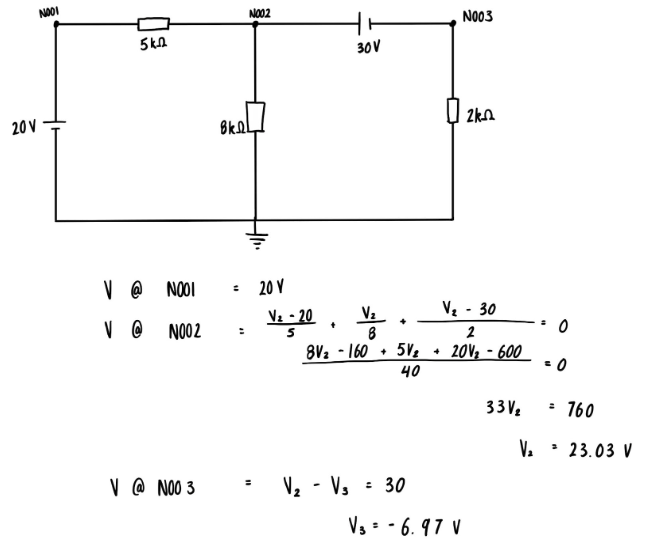
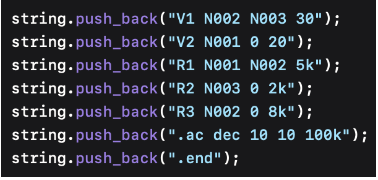
This is the circuit that we drew to test the conductance matrix. We then converted it into SPICE format according to the nodes in the drawing.
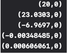
Also, the output shows the voltage at node 1 until node 3, then the bottom 2 values are the current through the 2 voltage sources, however, they are not needed in this case.
For a comprehensive understanding of the project, refer to the project report: View the PDF document