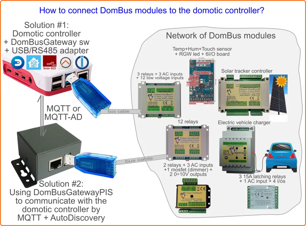
Gateway that interfaces one or more DomBus networks of home automation modules with MQTT AutoDiscovery
It's available in three ways:
- DomBusGateway software : python service that can be installed in any computer
- DomBusGateway addon for HAOS and Home Assistant Supervised
- DomBusGatewayPIS, a ready-to-use hardware connecting 1 or more DomBus buses, with LAN to exchange data by MQTT / MQTTAD
It's a custom protocol developed by Creasol to communicate with home automation modules using a RS485 serial bus, made by a standard alarm cable within 4 wires, 2 for data at 115200bps, 2 for 12-24V to supply all devices.
It's a multi-master protocol, where each DomBus module can start communicating to the controller for example when an input changes (for example a counter, alarm sensor, pushbutton), with a low latency (typically less than 100ms).
Also, it supports the so-called DCMD, commands sent between modules triggered by a input change or when a condition becomes true. DCMD can be used to realize simple automations that work even when the main controller (Domoticz, Home Assistant, ...) is frozen or OFF, similarly to KNX.
- High reliability and security
- Easy connection (thin alarm cable, 4x0.22mm², easy to route and connect)
- Exchange data, but also provides 13.8V power supply, with lead-acid backup battery for systems working also in case of blackout
- Very very low energy consumption: modules usually consume only 10÷15mW; relays module add about 60mW for each relay ON. Please compare with other systems!
They are very low power consumption devices with several versatile I/Os and sensors, performing general or specific functions, that can be used in building automations. They can be factory programmed with DomBus custom protocol, or Modbus standard protocol.
A list of DomBus modules can be found below.
DomBus modules equipped with DomBus protocol firmware can be used with:
- Domoticz, using the CreasolDomBus plugin
- Home Assistant Operating System, using the DomBusGateway addon
- Home Assistant, OpenHAB, NodeRED, ioBroker and other systems supporting MQTT, by using the DomBusGateway software that acts as a DomBus to MQTT-AD gateway.
- Any home automation system supporting MQTT protocol, by using the DomBusGatewayPIS microcomputer, providing DomBus2MQTT bridge
- Other building automation systems supporting Modbus protocol can use DomBus modules equipped with Modbus firmware.
DomBus firmware + DomBusGateway implementation is quick and simple, because all devices/entities are created automatically without any specific integration. Enable MQTT integration, start DomBusGateway software, connect one or more DomBus modules, and all DomBus ports are immediately visible in your home automation system. Also, DomBus protocol is a must in case that DCMD, pushbuttons, alarm sensors and counters are needed.
Modbus may be used for relay modules, EVSE module (to make your own electric vehicle charging wallbox using DomBusEVSE module), single or dual axis solar tracker (using DomBusTracker module). Modbus is not recommended in case that pushbuttons, alarm sensors and counters have to be used, because Modbus is a master-slave protocol where the controller have to poll continuosly all Modbus modules to get their input status, introducing delays.
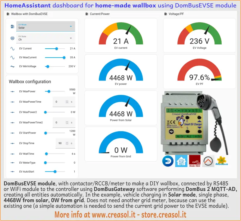
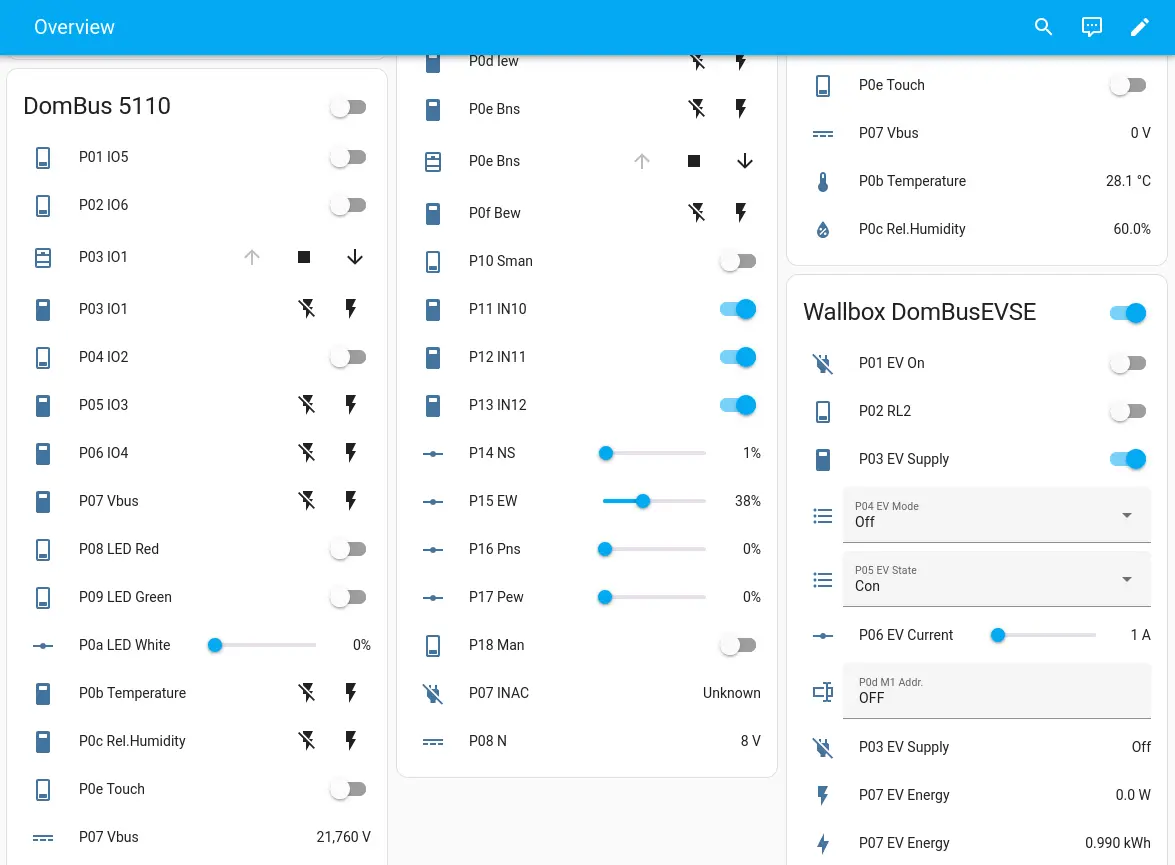
Using DomBusGateway software, hardware or add-on, Home Assistant is able to automatically create, read and manage all entities of the DomBusEVSE module: MQTT integration have to be enabled, of course!
Then it's possible to arrange entities in a custom dashboard as shown below:
Want to build a home-made, full features, EV charging station? Discover our KITs!
- KIT for single phase wallbox
- KIT for three phase wallbox
- More info about the DomBusEVSE module with Home Assistant
- More info about the DomBusEVSE module
- Also, please check the section DomBusEVSE module to build a DIY EV charger below
DomBusGateway software, hardware and addons work with one or more networks of DomBus modules equipped with DomBus protocol firmware. Modbus firmware is not supported!
Once executed, using the command python3 dombusgateway.py & , it opens one or more serial ports connected to DomBus modules (to get a reliable large network, it's possible to divide the DomBus network in trunks with 20-30 modules/each, or divide the building by floors/zones). It's also possible to use WiFi/LAN RS485 modules that provide a virtual serial interface, to get a wireless connection between the main controller where DomBusateway runs, and RS485 port physically connected to the DomBus modules.
If MQTT is enabled, it opens a connection to the MQTT broker to exchange data (sending device states and reading command from the domotic controller).
If TELNET port is enabled, the user can connect DomBusGateway by Telnet to check the network of modules and set configuration parameters for each module. DomBus modules usually have configurable I/Os, for example a I/O should be configured as digital input, analog input, counter, energy counter, and so on, and this configuration can be done by Telnet.
The software is still experimental, in development stage! Any contribution (testing and development) is welcome!
-
dombusgateway.py: main server that must be runned in background, calling python3 dombusgateway.py &
-
dombusgateway_const.py: script with several constants used by dombusgateway.py
-
dombusgateway_conf.py: configuration file that must NOT be changed by the user
-
local/dombusgateway_conf_local.py: local configuration file with custom configuration: this is the right place to store your local configuration, that will not be overwritten by git command
-
data/: directory, created if not existing, where list of DomBus modules and configuration is saved and restored
-
/var/log/dombusgateway: directory where logs are stored
-
/etc/systemd/system/dombusgateway.service: service configuration file for systemd
From the shell, run the command:
sudo bash -c "$(curl -sSfL https://creasol.it/DBGinstall)"
that will automatically install the package in /opt/DomBusGateway and run it from systemd.
DomBusGateway daemon then can be stopped and started by systemd, using the commands:
systemctl stop dombusgateway
systemctl start dombusgateway
When installed, to update the software with the last version, it's sufficient to enter the following commands:
cd /opt/DomBusGateway; git pull; systemctl restart dombusgateway
In this case the DomBusGateway addon should be installed: click on https://github.com/CreasolTech/homeassistant-addons and check the DomBusGateway section.

It's also possible to find some images for SBC/MiniPC that will be used as a real DomBusGateway hardware, with USB port to connect a DomBus network of modules by one USB/RS485 adapter, or to connect a USB hub in case that more USB ports are needed, and one LAN port or WiFi to connect the home automation system by MQTT or MQTT-AD.
The ready-to-use device, with Linux + DomBusGateway + Mosquitto already installed, can be purchased from store.creasol.it . It's based on the Rock PI S hardware, a tiny ARM computer with only 400mW power usage, 4 cores, 512MB RAM.
Alternatively, it's possible to download the following files:
- https://docs.creasol.it/dombusgatewaypis.sfdisk
- https://docs.creasol.it/dombusgatewaypis.boot.img.gz
- https://docs.creasol.it/dombusgatewaypis.fsa
and from the shell of a linux computer write the following commands to write a 64GB (or more) microSD:
export disk=/dev/sdX   (replace x with the number associated to the microSD device)
zcat dombusgatewaypis.boot.img.gz >${disk}
sfdisk $disk < dombusgatewaypis.sfdisk
fsarchiver -v restfs dombusgatewaypis.fsa id=0,dest=${disk}1 id=1,dest=${disk}2
Then put the microSD in the Rock PI S hardware and enjoy!
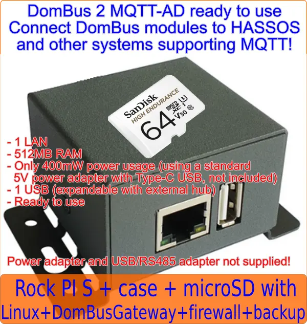
The Rock PI S is programmed with a Linux firmware that minimize writing to disk, by having /tmp and /var/log partitions in ramfs (volatile memory): in this way the microSD life will be extended.
It's possible to access the operating system by SSH (port 22), connecting the IP addressed assigned by DHCP (check the router or scan the network to find its IP address) using:
username: pi , password: arangingenni
username: root , password: geriandallse
Login by SSH protocol using pi user, then type sudo su - to get root priviledges. Passwords can be modified by using the passwd command, of course.
Also, the system runs mosquitto MQTT broker that can be accessed on port 1883 with the following credentials:
username: dombus
password: secretpasswd
To disable mosquitto service, just run sudo systemctl disable mosquitto
Connect to the host running DomBusGateway by using the SSH protocol: ssh pi@192.168.1.123 or use putty from Windows.
cd /opt/DomBusGateway/local to enter the configuration directory
nano dombusgateway_conf_local.py to modify the configuration file, where several parameters are stored, like:
-
dataDir: persistent directory where devices data is stored. Set to /data in case of HAOS
-
debugLevel: verbosity of debug information
-
buses: list of DomBus buses serial interface name (normally /dev/ttyUSB0 in case that only 1 bus is used)
-
mqtt: parameters for the MQTT broker connection
-
telnet: parameters for the telnet interface
It's possible to connect dombusgateway by telnet in this way: first connect to the host running DomBusGateway by using SSH protocol, then type
telnet localhost 8023
Telnet commands:
-
help : print list of commands
-
refresh : send list of all devices to the domotic controller
-
refresh reset : all DomBus entities are removed and created as new, so you can loose configuration, entity names, ...
-
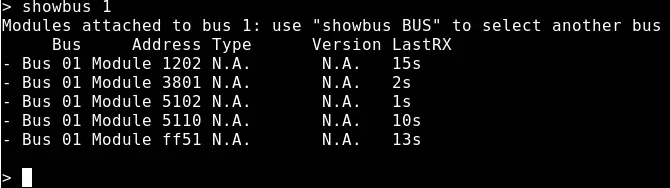
showbus BUS : list modules attached to the specified bus (it's possible to connect 20-30 modules to the same bus, but for safety reasons it can be good to differentiate bus by floors or by area to manage very large buildings). For example showbus 2 to list modules attached to bus #2
-
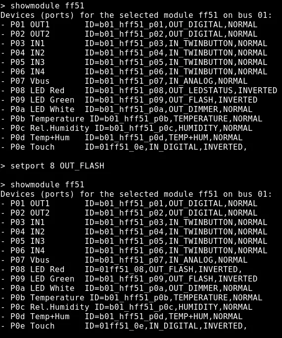
showmodule ADDR : list ports associated to the specified module. For example showmodule 3701 to list ports and configuration for the module with address 3701. In case that more than 1 bus is installed, this command should be performed after a showbus N module to select the bus number N, or the first bus will be automatically selected.
-
setport 1 HWADDR=101 : set the new address 101 for the current module. A unique address should be specified, in hex format, from 1 to efff.
-
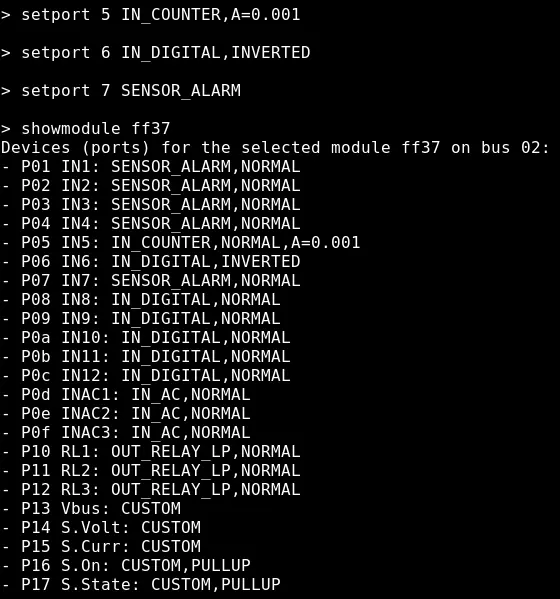
setport PORT CONFIGURATION : change the configuration of the specified port. For example setport 1 IN_COUNTER,DIVIDER=2000 to configure port1 in counter mode, type energy meter with pulsed output, 2000 pulses / kWh. This command can be issued only after a showmodule ADDR to select the appropriate module.
In www.creasol.it it's possible to check information about the module to know which configurations can be assumed by each port (check the associated table). Also, in case of Home Assistant, it's possible to define for each port the desired platform and class, in this way:
setport 7 IN_DIGITAL,p=binary_sensor,device_class=motion if port 7 is connected to a PIR (infrared motion sensor) and port have to be configured as binary_sensor with motion class
setport 7 device_class=motion if the port is already configured as input and only the class have to be changed
setport 7 SENSOR_ALARM,device_class=motion if the PIR is a double-biased or triple-biased type
setport 4 IN_ANALOG,FUNCTION=3950 if port 4 is connected to a NTC thermistor 10k with B=3950 coefficient
setport b CAL=-0.3 to calibrate temperature sensor on a DomBusTH (port b, 11 in decimal) if the real temperature is 0.3°C below. setport b CAL=0 to remove any calibration
setport 1 INIT=1 to set TrackerType=1 parameter on the DomBusTracker (to configure as a Single Axis Horizontal tracker)
setport 19 INIT=180 to set TrackerPeriodCheck=180 seconds on port 19 (25 in decimal)
setport d ADDR=2 to set meter address from 1 (default) to 2 (for the EV meter) on a DomBusEVSE
setport d ADDR=3 to set meter address from 1 (default) to 3 (for the Grid meter) on a DomBusEVSE \ setport c ADDR=1 to set meter address from 3 to 1 on a DomBusEVSE \ setport b ADDR=1 to set meter address from 2 to 1 on a DomBusEVSE -
quit: exit from telnet session.
Assure that software/addon is running. Also check the Log
Normally debugLevel is 7, but it can be increased to 15 (debug), 63 (debug + DomBus RX/TX), 399 (debug + MQTT TX/RX)
Restart DomBusGateway and check in the Log that serial port exists and is opened correctly
cd /opt/DomBusGateway
git pull
systemctl restart dombusgateway
Wiring diagrams to make the charging station, single phase or three phase, is available at www.creasol.it/EVSE
The EVSE module is programmed to work, by default, with two energy meters (one to measure the Grid power, and one to measure the EV power, energy, voltage, PF) connected to the 2nd RS485 bus available on the module: in this case the charging station can work independently from the home automation system.
As most probably the user already have an energy meter measuring grid power (sometimes included in hybrid solar inverters), it's possible to avoid installing a new energy meter for the grid power by implementing a simple automation that sends the current value of power from the grid, positive when importing energy, negative when exporting, to the P0c Grid Power entity. Similarly, for buildings having a stationary battery, it's good to send to the EVSE module the value Power_from_the_grid + Power_from_the_battery : in this case, when charging the EV in Solar mode, the EVSE module works to have P0c Grid Power=0 that means "do not use energy from the grid, nor energy from the stationary battery, but consume only energy from the photovoltaic". The same in case of wind, hydro or other power sources. In this case the charging station needs that home automation system works, sending the right value of power from the Grid or Grid-Battery. In this case you have to configure P0c Grid Power as a number entity, in this way:
- open a telnet connection with DomBusGateway telnet localhost 8023
- select bus, if needed (default=bus1) showbus 2
- select EVSE module showmodule ffe3
- set port 0c as platform number, with min value = -12000W and max value = 12000W (depending by your solar and contractual power) setport c p=number,min=-12000,max=12000
Bidirectional pulse miter, with pulse outputs connected to DomBus12 on io7 (imported energy) and io8 (exported energy)
This automation sends the value ImportPower - ExportPower to the P0c Grid Power entity:
- id: '1750798854962'
  alias: power2wallbox
  description: 'Sends Grid power value to the wallbox'
  triggers:
  - trigger: state
    entity_id:
    - sensor.dombus_1201_p07_io7	# Grid import power value (0 while exporting)
    - sensor.dombus_1201_p08_io8	# Grid export power value (0 while importing)
  conditions: []
  actions:
  - service: number.set_value
    target:
      entity_id: number.dbevse_ffe3_on_bus_2_p0c_grid_power		# Entity name of P0c EVSE module
    data:
      value: >
        {{ (states('sensor.dombus_1201_p07_io7') | float) - (states('sensor.dombus_1201_p08_io8') | float) }}
  mode: single
Software is written by Creasol, https://www.creasol.it with the valuable help of:
- Alex Adam, for debugging
- Cristiano, for debugging
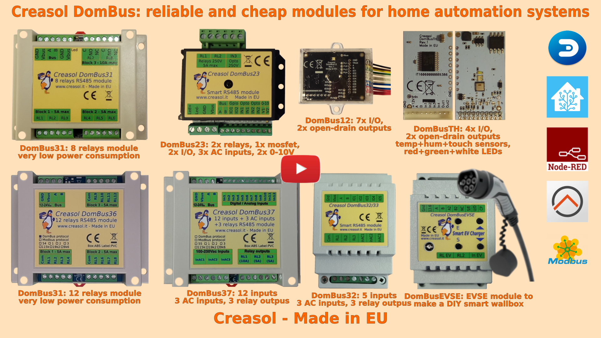
Below a list of modules, produced in Italy by Creasol, designed for high reliability and optimized for very very low power consumption.

Our industrial and home automation modules are designed to be
- very low power ⇒ 10÷15mW with relays OFF
- reliable ⇒ no disconnections
- wired network (bus) ⇒ no radiofrequency interference, no battery to replace
Modules are available in two versions:
- with DomBus proprietary protocol, suitable for every type of DomBus modules, working with Domoticz by using the Creasol DomBus plugin, and Home Assistant, OpenHAB, Node-RED ... by using the DomBusGateway software, a DomBus 2 MQTT-AutoDiscovery interface
- with Modbus standard protocol, suitable for relays modules, EVSE and Dual Axis solar tracker, working with almost any building automation system supporting Modbus
What version is the best? DomBus version, because:
Modbus is a standard protocol Master/Slave: the controller must poll each module to get its status, so it's not suitable to manage inputs and counters that change frequently, but can be used to manage relay outputs or read inputs status every 2-5s
DomBus is a proprietary multi-master protocol where each module is able to initiate the communication with the master to notify, for example, an input change, with a short latency (<100ms) that permits to manage alarm sensors in a reliable way. Also, DomBus supports the so-called DCMD, commands exchanged between modules as KNX does, so it's possible to program simple automations that work between modules even if the domotic controller is OFF (for example, short pulse on button to toggle a light ON/OFF, 1s pulse to open the garage door, 2s pulse to turn OFF some lights, ...)
Store website - Information website
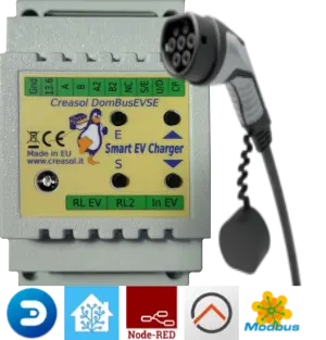
- Single-phase and three-phase, up to 32A (8kW or 22kW)
- Needs external contactor, RCCB (protection) and EV cable
- Optional power meter to measure charging power, energy, voltage and power factor
- Optional power meter to measure the power usage from the grid (not needed if already exists)
- Two max grid power thresholds can be programmed: for example, in Italy who have 6kW contractual power can drain from the grid Max (6* 1.27)=7.6kW for max 90 minutes followed by (6* 1.1)=6.6kW for another 90 minutes: in this case the EVSE module can drain ALL available power when programmed to charge at 100% minimizing the charge time and increasing the charging efficiency.
- Works without the domotic controller (stand-alone mode), and can also work in managed mode, with an automation in the home automation system setting the charging current
DomBusTH - Compact board to be placed on a blank cover, with temperature and humidity sensor and RGW LEDs
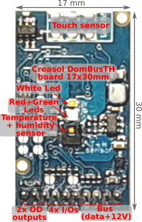
Includes:
- temperature and relative humidity sensor
- red, green and white LEDs
- 4 I/Os configurable as analog or digital inputs, pushbuttons, counters (water, gas, S0 energy, ...), NTC temperature and ultrasonic distance sensors
- 2 ports are configured by default as open-drain output and can drive up to 200mA led strip (with dimming function) or can be connected to the external module DomRelay2 to control 2 relays; they can also be configured as analog/digital inputs, pushbuttons and distance sensors.
- analog/digital inputs
- pushbutton and UP/DOWN pushbutton
- counters (water, gas, S0 energy, ...)
- NTC temperature and ultrasonic distance sensors
- 2 ports are configured by default as open-drain output and can drive up to 200mA led strip (with dimming function) or can be connected to the external module DomRelay2 to control 2 relays.
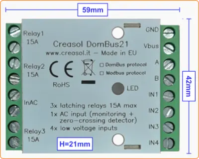
- 3x latching relays SPST, max current 15A (3kW): no power consumption when relays are On or Off!
- 1x 230V AC opto-isolated input to detect 230V and power outage, with zero-detection to switch relays/loads minimizing in-rush current
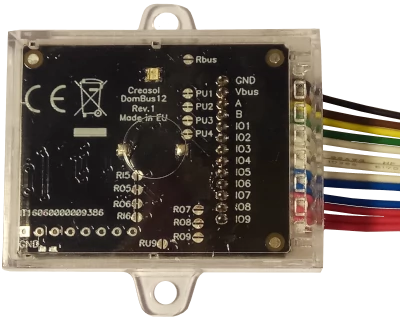
- 4x I/O lines, configurable as analog/digital inputs, temperature/distance sensor, counter, meter, ...
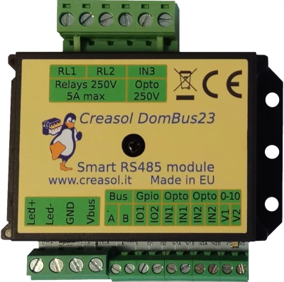
- 2x relays SPST 5A
- 1x 10A 30V mosfet (led stripe dimming)
- 2x 0-10V analog output: each one can be configured as open-drain output to control external relay
- 2x I/O lines, configurable as analog/digital inputs, temperature/distance sensor, counter, ...
- 2x low voltage AC/DC opto-isolated inputs, 9-40V
- 1x 230V AC opto-isolated input
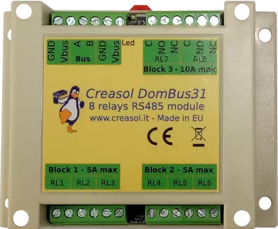
- 6x relays SPST 5A
- 2x relays STDT 10A
- Only 15mW power consumption with all relays OFF
- Only 600mW power consumption with all 8 relays ON !!
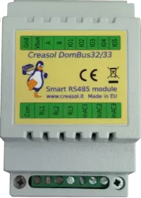
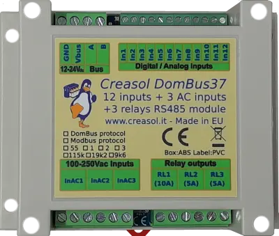
- 3x relays SPST 5A
- 3x 115/230Vac optoisolated inputs
- Single common for relays and AC inputs
- 5x general purpose I/O, each one configurable as analog/digital inputs, pushbutton, counter, temperature and distance sensor.
- 3x relays SPST 5A
- 3x 115/230Vac optoisolated inputs
- Single common for relays and AC inputs
- 5x general purpose I/O, each one configurable as analog/digital inputs, pushbutton, counter, temperature and distance sensor.
Each relay can toggle the existing step-relay, switching the light On/Off. The optoisolator monitors the light status. The 5 I/Os can be connected to pushbuttons to activate or deactivate one or all lights.
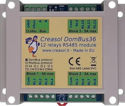
- 12x relays SPST 5A
- Relays are grouped in 3 blocks, with a single common per block, for easier wiring
- Only 12mW power consumption with all relays OFF
- Only 750mW power consumption with all 12 relays ON !!
- 12x low voltage inputs (analog/digital inputs, buttons, alarm sensors, balanced double/triple biased alarm sensors, counters, meters, temperature and distance sensors, ...)
- 3x 115/230Vac optoisolated inputs
- 2x relays SPST 5A
- 1x relay SPST 10A
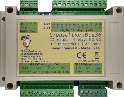
- 12x low voltage inputs (analog/digital inputs, buttons, alarm sensors, balanced double/triple biased alarm sensors, counters, meters, temperature and distance sensors, ...)
- 1x 115/230Vac optoisolated input to detect power outage and for zero-crossing detection (to switch relays minimizing the in-rush current)
- 4x relays SPDT 10A (with Normally Open and Normally Closed contacts)
- 2x relays SPST 10A (with only Normally Open contacts)
DomBusTracker - Dual axis sun tracker controller working with Domoticz, Home Assistant, Node-RED, Modbus, ... and also working in standalone with no external controllers
Module that check a deep-hole sun sensor to detect the direction of maximal sun radiation, working also in case of cloudy weather.
- Controls two external actuators/motors (linear or not) to move motors to reach the best tilt / elevation and azimuth position to optimize photovoltaic production.
- Check current through the motors to detect internal limit switch (useful for linear actuators) and find where the tracker reach the final/initial position.
- Works autonomously (stand-alone), without any home automation system controller, but also can be connected to a home automation system using Domoticz, Home Assistant, NodeRED, OpenHAB, and other systems by using the DomBusGateway software (that converts DomBus protocol to MQTT AutoDiscovery), or with other systems by using DomBusTracker with Modbus firmware.
- Wire connection (RS485) to the domotic controller for the best reliability.
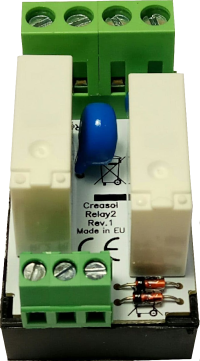
- 2x SPST relays 5A (Normally Open contact)
- Overvoltage protection (for inductive loads, like motors)
- Overcurrent protection (for capacitive laods, like AC/DC power supply, LED bulbs, ...)
- 9÷24V power supply input, with high efficiency DC/DC regulator with 5V output
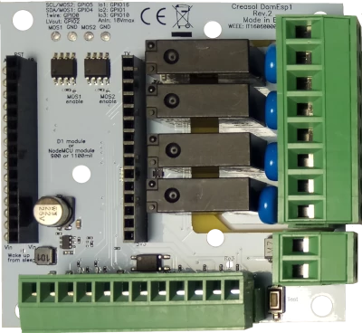
- 4x SPST relays 5A with overvoltage protection (varistor)
- 2x mosfet outputs (max 30V, 10A) for LED dimming or other DC loads
- 1x I²C interface for sensors, extended I/Os and more)
- 1x OneWire interface (DS18B20 or other 1wire sensors/devices)